I Shrink the tubing with a heat gun.
J Insert the cable ends through the liquid tight connectors and tighten the nuts.
K Secure the cables internally using a Clamp as shown in Figure 4-13: Clamp Views. Make
certain that the drain wire makes contact with the Clamp’s metallic surface.
L Clip the exposed drain wires flush with the Clamps.
M Connect the conductors to the terminal block as listed in Table 4-4: Processor Circuit Board
Terminal Strip Color Coded Connections for Tachometer.
4.4.6 Locations 10 and 11 Installation
4.4.6.1 Clutch Cable (Location 10)
A single four-conductor cable must connect the two Shift cables to the Processor through a 12 pin
plug.
4.4.6.1.1 Processor Termination
A Install a liquid tight connector into hole no.10.
B Run a 32 inch (0,82m) piece of four-conductor cable through the liquid tight
connector and tighten, leaving 16 inches (0,41m) outside of the Processor.
C Strip back 4 inches (101,6mm) of the PVC jacket inside the Processor.
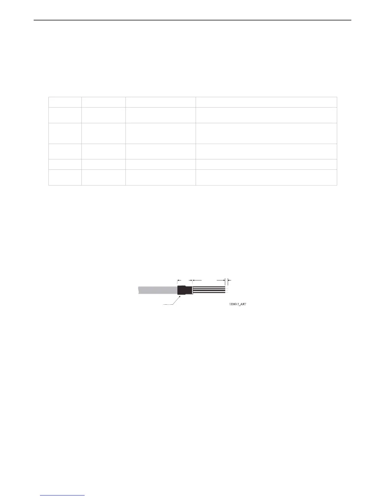
D Slide a 1 inch (24,5mm) piece of heat shrink over the end of the cable as
shown in Figure 4-20: Clutch Cable Heat Shrink in Processor.
Figure 4-20: Clutch Cable Heat Shrink in Processor
E Strip back 3/8 inch (9,53mm) from the four conductors and connect to the
Processor as shown in Table 4-5: Clutch Termination Table.
Table 4-4: Processor Circuit Board Terminal Strip Color Coded Connections for Tachometer
Termination Conductor Color Description Notes
TB9-1 Red Sensor Supply (+9VDC)
Required when Open Collector (i.e., Hall Effect Sensors)
only
TB9-2 Green AC Type Tachometer Input
The green wire connects here when AC Type Tach Sensors
(i.e., Mechanical Senders, Magnetic Pickup, Alternator AC,
etc.) are being used.
TB9-3 Green
Open Collector Tachometer
Input
The green wire connects here when an Open Collector Type
Tach Sender is used.
TB9-4 Black Return for Tachometer Input Negative connection for both types of Senders.
Clamp Silver
Drain wire (Shield)
connection.
Connection made at Processor side only.
12263.7_ART
Heat Shrink
1 inch
(25,4mm)
4 inches
(101,6mm)
3/8 inch
(9,53mm)

 Loading...