L Connect the conductors to the terminal block as listed in Table 4-3: Processor Circuit Board
Terminal Strip Color Coded Connections for Serial Communication
4.4.5.5 Tachometer Cable (Location 9)
A Run a two- or three-conductor shielded cable from the Port Processor to the Port engine’s
tachometer source. (Refer to Section Section 3.1.4: Tach Sensor Harness)
B Run a two- or three-conductor shielded cable from the Starboard Processor to the Starboard
engine’s tachometer source.
C Install a 1/2 inch (12,7mm) liquid tight cable grip into hole (No. 9) of the Port and Starboard
Processors. (Refer to Figure 4-5: Standard Enclosure Cable Holes for entry hole location and
Figure 4-4: Liquid Tight Installation for cable grip installation)
D Strip back 2 inches (50,8mm) of PVC jacketing from both ends of the cable.
E Strip the ends of each conductor back 3/8 inch (9,5mm).
F Clip off the drain wire flush with the PVC jacketing at the Tachometer source side
only.
G Place a 7/8 inch (22,23mm) section of shrink tubing over each end of the cable.
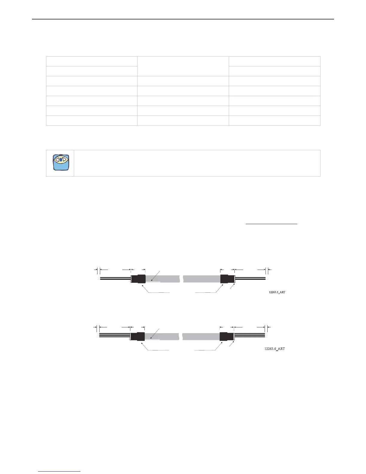
H At the Processor side, bend the drain wire back and tuck it under the shrink tubing so that
the grain wire end is exposed past the shrink tubing. (Refer to Figure 4-18: AC Type
Tachometer Cable and Figure 4-19: Open Collector Tachometer Cable).
Figure 4-18: AC Type Tachometer Cable
Figure 4-19: Open Collector Tachometer Cable
Table 4-3: Processor Circuit Board Terminal Strip Color Coded Connections for Serial Communication
PORT PROCESSOR
Conductor Color
STARBOARD PROCESSOR
Termination A Termination B
TB7-6 White TB7-6
TB7-7 Green TB7-7
TB7-8 Red TB7-8
TB7-9 Black TB7-9
Clamp Silver (Drain Wire) No Connection
NOTE: Three-conductor cable is required with Open Collector Type (Hall Effect) Tachometer Senders only.
Heat Shrink
12263.5_ART
1 inch
(25,4mm)
3.5 inches
(88,9mm)
3/8 inch
(9,53mm)
Wrapped Drain Wire
Clip Drain Wire
1 inch
(25,4mm)
3.5 inches
(88,9mm)
3/8 inch
(9,53mm)
PROCESSOR TACHOMETER SENDER
Heat Shrink
12263.6_ART
1 inch
(25,4mm)
3.5 inches
(88,9mm)
3/8 inch
(9,53mm)
Wrapped Drain Wire
Clip Drain Wire
1 inch
(25,4mm)
3.5 inches
(88,9mm)
3/8 inch
(9,53mm)
PROCESSOR TACHOMETER SENDER

 Loading...