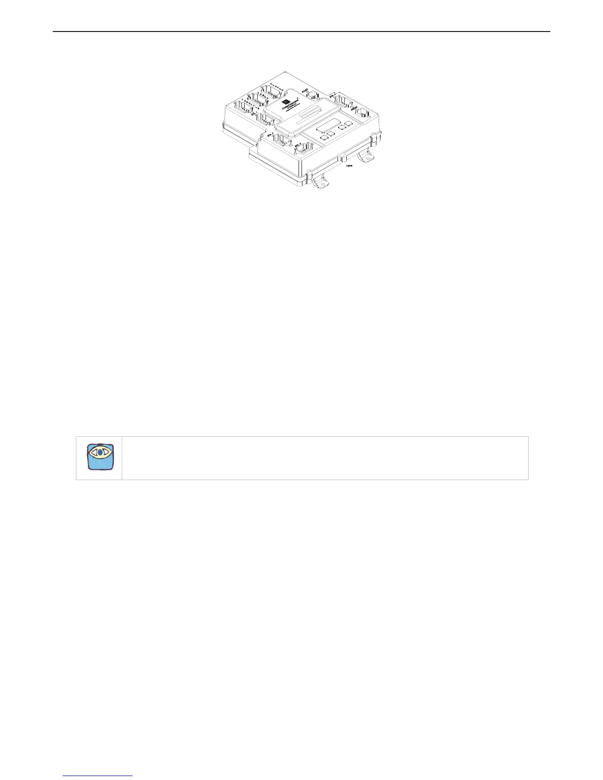
Figure MMC-343-1: Station Expander
The station expander (SE) is designed to be an addition to the 9000 Series / CruiseCommand Processors.
The station expander allows the user to install more than the maximum allowed control heads (up to four).
MMC-343: 1 Features
• Station-in-Command Indication
• Audible and Visual Indicators
• Key-Pad Set Up
• Plug-in Cable Connections
• Built-in Diagnostics
• Addition of One to Four Remote Stations
The Station Expander receives the variable DC voltage from the Control Head(s) and serially communicates
these inputs to the Processor.
MMC-343: 2 Required Parts
• One Station Expander required per Processor.
• Mounting Hardware is installer supplied.
• System Operation Manual included with the Processor.
MMC-343: 3 Location
• Expanders are spray proof, but must not be immersed.
• An engine room location of the Expanders is preferred.
• If the engine room is too small, locate in any area where it is accessible for electrical connections.
Bulkhead mounting preferred for ease of access for wiring and adjustments.
The Expander can be mounted in any attitude as long as the LED on the front cover is readable.
Do not mount the Expander on the engine, on the transmission, or in any location that will subject it to
excessive vibration.
Refer to Figure MMC-343-4: Station Expander Dimensions, for Expander dimensions.
NOTE: Read the MMC-165 Warranty in section 12: Appendix B - Sales and Service Information. Improper
mounting location may cancel warranty.