B Activate Set Up Mode.
C Scroll Up or Down to the desired Value.
D Store the Value to memory.
Figure 5-20: Display LED Function E7 Set Up Activated
5.7.0.1 Throttle Servo Functions
This section along with Section 5.6.2.1: Throttle Basic Functions allows the adjustment of Throttle
Servo related items:
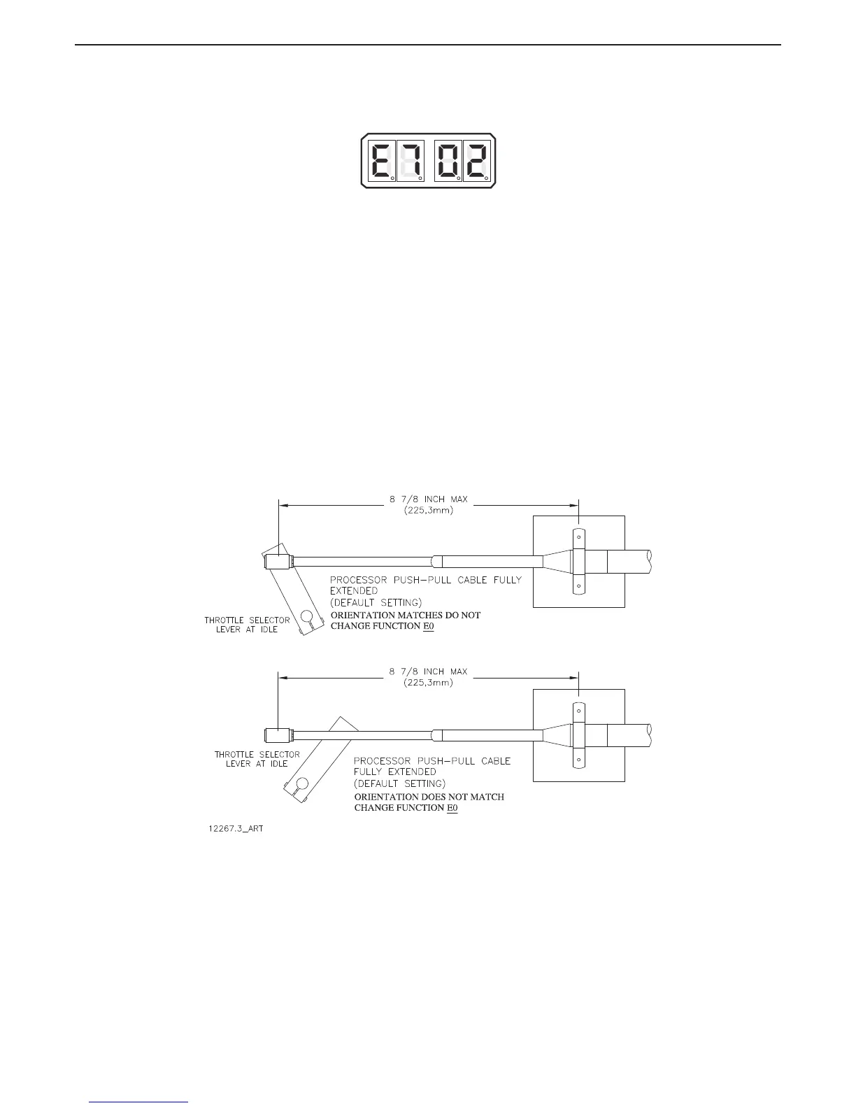
5.7.0.1.1 Function Code E0 – Throttle Servo Direction
This Function determines if the Throttle Push-Pull cable is fully extended or retracted when
at Idle.
The available Values for this Function are:
20 Fully Retracted [Pull] at Idle (Default Value)
21 Fully Extended [Push] at Idle
To determine and change the Value (Refer to Sections Section 5.2: Activating Set Up Mode
and Section 5.3: Storing Values To Memory):
A Ensure that the engine’s Governor or Carburetor lever is at the Idle position.
• If the Throttle Push-Pull cable’s ball joint is close to the Throttle
lever’s position, no change is required to this Function Code.
• If the Throttle Push-Pull cable’s ball joint is at the opposite side of
the lever’s position, continue with the next step.
Figure 5-21: Throttle Push-Pull Cable Orientation