5.7.2.1.10 Function Code L6 – Solenoid Troll Pulse Percentage
This Section along with the Basic Troll Command Functions allows the adjustment of the
Processor’s Solenoid Troll command.
Function Code L6 selects the percentage of available Troll signal when first engaging the
Clutch while in Troll.
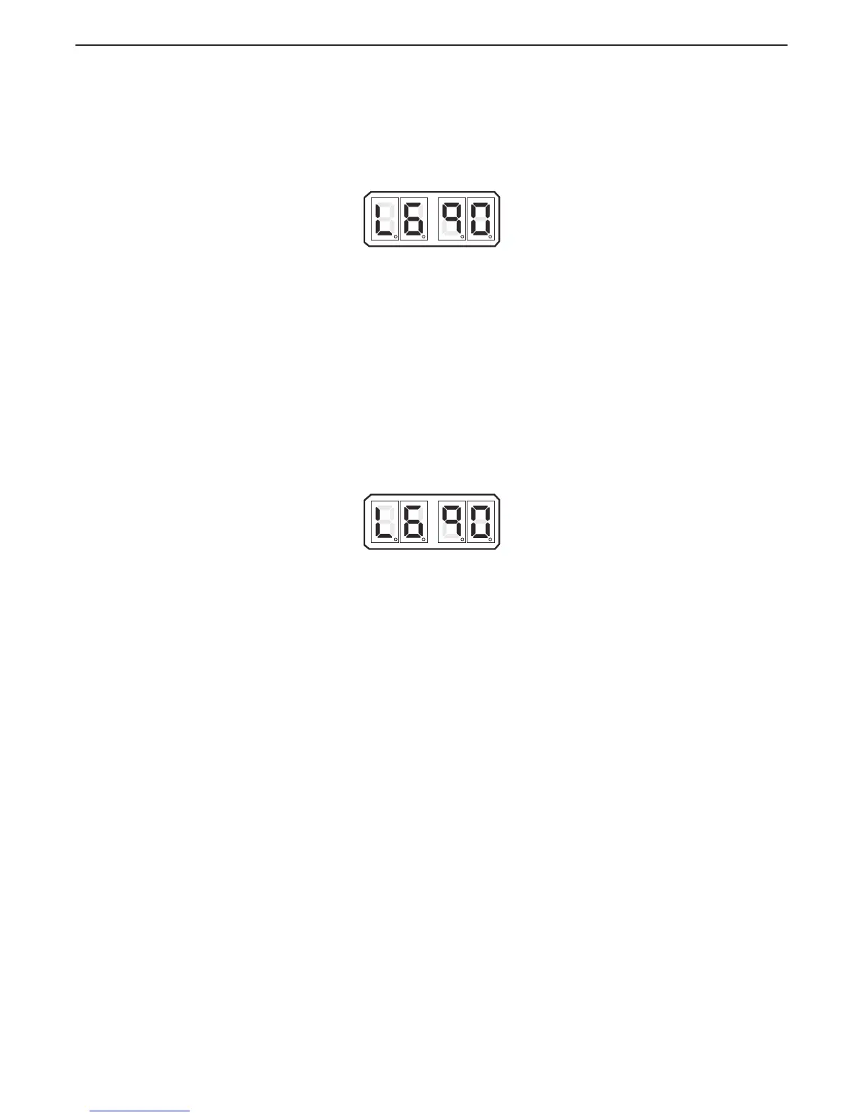
The available Values for this Function are 01.0% to 100.0%
The default Value is 90.0%.
Figure 5-56: Display LED Function L6 Set Up Activated
A With Troll selected, place the Control Head lever into the Ahead detent.
• If the vessel lunges forward or the shaft takes too long to start
rotating, continue with the next step.
B Scroll to Function Code L6.
C Activate Set Up Mode.
D Scroll Up or Down to the desired Value
E Store the Value to memory
5.7.2.1.11 Function Code L6 – Servo Troll Pulse Percentage
This Section along with the Basic Troll Command Functions allows the adjustment of the
Processor’s Servo Troll command.
This Function Code selects the percentage of available Troll Servo Range the Processor’s
push-pull cable travels when first engaging the Clutch while in Troll.
The available Values for this Function are 01.0% to 100.0%
The default Value is 90.0%.
Figure 5-57: Display LED Function L6 Set Up Activated
A With Troll selected, place the Control Head lever into the Ahead detent.
• If the vessel lunges forward or the shaft takes too long to start
rotating, continue with the next step.
B Scroll to Function Code L6.
C Activate Set Up Mode.
D Scroll Up or Down to the desired Value
E Store the Value to memory