2 Procedure
2.1 Throttle Signal Testing
Depending on which Processor is being tested, it may have the capability of sourcing one or all of the
following: DC Voltage, Current, PWM (Pulse Width Modulation) or Frequency.
2.1.1 DC Voltage
A Ensure that power is removed from the Engine Electronics and the Processor.
B Disconnect the Throttle Harness from the number 1 Processor connector/pigtail.
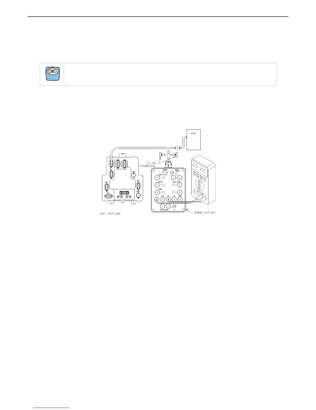
C Insert the Break-out Box between the number 1 Processor connector/pigtail and the Throttle
Harness as shown in Figure MM13927-4: Throttle Connection (DC Voltage).
Figure MM13927-4: Throttle Connection (DC Voltage)
D Set up the Multimeter to measure DC Volts and plug the black lead into the Break-out Box
black socket labeled “-” and the red lead into the socket labeled “VDC”.
E Turn power ‘On’ to the Processor and take command at any Remote Station.
F The appropriate Idle Voltage for the application should be measured at this time.
G Move the Control Head lever to the Full Throttle position while depressing the Transfer
Button (Throttle Only Mode).
H The appropriate Full Throttle Voltage for the application should be measured at this time.
2.1.2 Current (mA)
A Ensure power is removed from both the Engine Electronics and the Processor.
B Disconnect the Throttle Harness from the number 1 Processor connector/pigtail.
C Insert the Break-out Box between the number 1 Processor connector/pigtail and the Throttle
Harness as shown in Figure MM13927-5: Throttle Connection (Current mA).
NOTE: The following procedures and drawings pertain to both the CruiseCommand and ClearCommand
Processors.