3. Standard Cable
A Remove the six screws holding the bottom cover of the Control Head housings and set aside.
B Insert cable through the correct cable grip in the bottom cover.
C Strip
back the PVC cover on the shielded cable approximately 2-1/2” (63,5mm) at the Control Head.
D At the Control Head end of the cable strip and cut off
the shielding and drain wire flush with the end
of the PVC cover (the drain wire at the Control Head is not
connected to ground).
E Strip
3/8” (9,5mm) insulation off each wire.
F Twist
the individual strands of the wires to minimize fraying.
G Crimp
a locking fork terminal (included with each Control Head) to each of the conductors.
Make connections
to the Control Head as indicated in the following TERMINAL CONNECTIONS diagrams.
4. Pluggable
A Plug Control Head cable into the pigtail at the Control Head. (Ensure the correct Processor Cable is
being plugged into the corresponding Control Head lever pigtail).
B When connecting the plugs, ensure that the release button or buttons are depressed and held
until
plug is fully connected or disconnected. Connecting or disconnecting plugs without depressing and
holding the release button or buttons will damage the plug.
ALWAYS REFER TO THE MANUAL THAT IS SUPPLIED WITH THE CONTROL SYSTEM FOR ANY UNIQUE
CONTROL HEAD CONNECTIONS FOR YOUR SYSTEM.
When cable connections are complete:
A Replace
Control Head bottom cover using the six (6) mounting screws removed earlier. Ensure seal is
in place.
B Tighten
watertight cable grip(s).
C Remove
front cover from the Control Head
D Mount
Control Head with supplied hardware.
E Replace
front cover when mounting is complete.
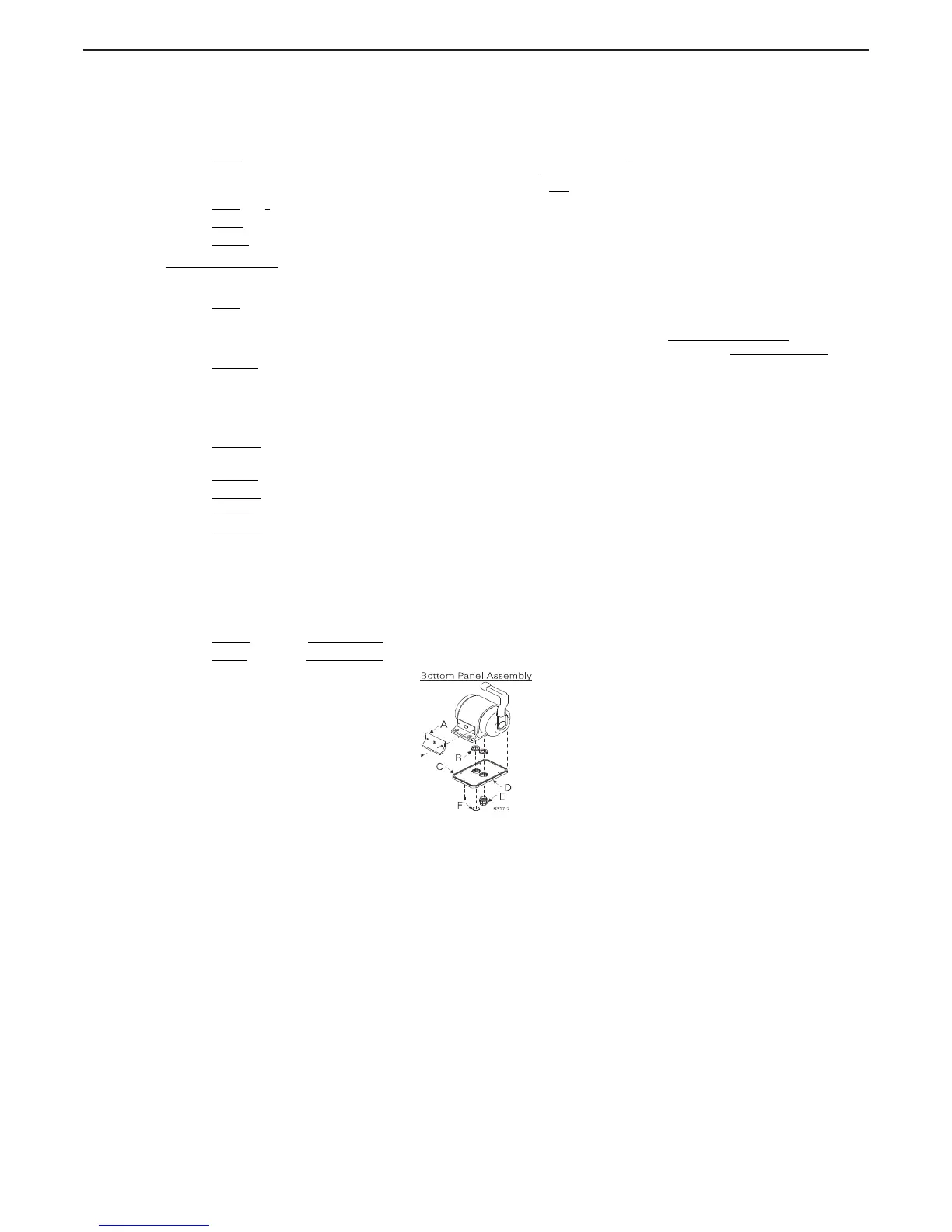
5. Bottom Panel Assembly Designations
A Front Cover
B Cable Grip Nut
C Seal
D Bottom Cover
E 750-R
= Plug; 750-L & 760 = Watertight Cable Grip (Cable O.D..275 -.393 [7mm - 10mm)
F 750-L
= Plug; 750-R & 760 = Watertight Cable Grip (Cable O.D..275 -.393 [7mm - 10mm)

 Loading...