Service Kit Installation Procedures
4–48 www.zoll.com 906-0731-04-01 Rev. C
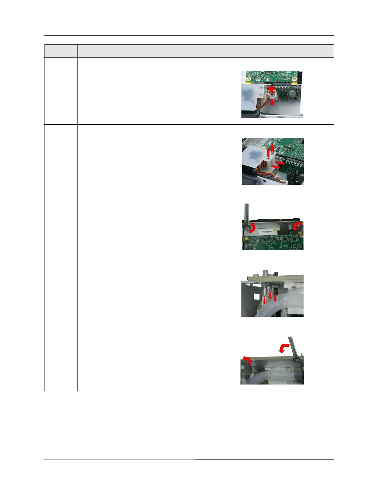
7 Disconnect the Power Input cable by pressing on
the locking latch and pulling the cable straight up
from the connector.
8 Loosen and remove the two 4-40 x 1 1/4 screws
and nylon spacers supporting the Power Input
assembly unto the chassis.
Save these screws and spacers.
9 Loosen and remove the two 6-32 Keps nuts using a
5/16 open-end wrench.
10 Using smooth jaw needle nose pliers, carefully
remove the 3 tubing on these fittings:
• “Transducer”
• “Exhaust Do not Occlude”
• “Exhalation Valve”
Do not discard the tubing.
11 Loosen and remove the two 6-32 Keps nuts using a
5/16 open-end wrench.
Step Action