Service Kit Installation Procedures
906-0731-04-01 Rev. C ZOLL Ventilator Service Manual 4–49
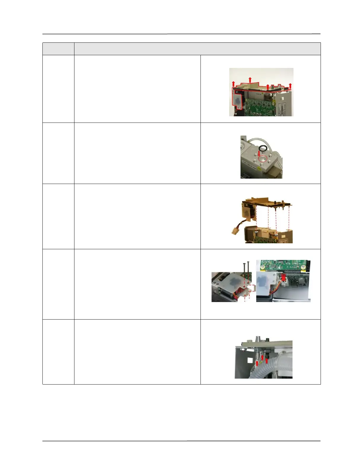
12 Lift the damaged connector panel assembly out
from the SPM.
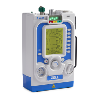
13 Remove and discard the 1/2" OD x 3/8" ID O-ring
from the Oxygen Inlet manifold. Place the new 1/
2" OD x 3/8" ID O-ring in the Oxygen Inlet
manifold.
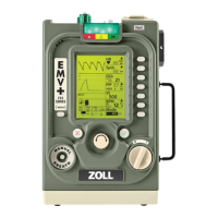
14 Position the replacement Connector Panel over
the SPM and secure with the four
6-32 Keps nuts (provided in the kit).
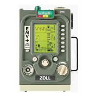
15 Secure the Power Input assembly to the Chassis
using the two spacers and
two 4-40 x 1 1/4 screws.
Note: Do not over-tighten the screws.
(Maximum torque - 3.5 in.- lb.)
Connect the Power Input cable by inserting into
connector.
Insure that locking latch engages.
16 Insert the 3 tubing to their correct connectors.
• “V_BACKUP” to “Exhalation Valve”
• “V_ACAL” to “Transducer”
• “Exhaust Do Not Occlude” (smallest tubing)
Step Action