Service Kit Installation Procedures
4–82 www.zoll.com 906-0731-04-01 Rev. C
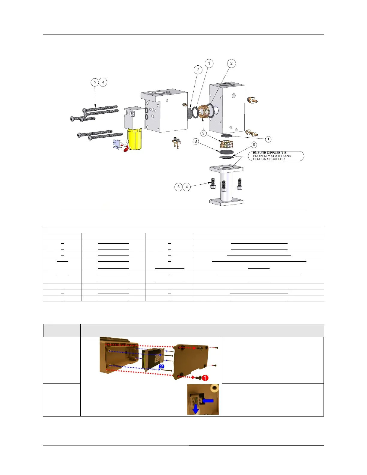
Manifold Diagram
Remove the Main Battery
Kit Contents
ITEM PN QTY DESCRIPTION
1
340-0023-00 2 O-Ring ½” OD X 3/8” ID
2 340-0059-00 1 O-Ring 5/8” OD X ½” ID
3 340-0061-00 1 O-Ring 5/8” OD X 7/16” ID
5 + 4 358-0440-28
602-0006-00
4
As Required
SCREW, PHILIPS, PAN HEAD, 4-40 x 1 ¾
Vibratite
6 + 4 360-0632-05
602-0006-00
4
As Required
SCREW, CAP, SOCKET, 6-32 x 5/16
Vibratite
7 465-0013-00 1 Diffuser 0.484 Diameter
8 465-0029-00 1 Diffuser 0.615 Diameter
9 804-0006-00 2 Flow Screen, 400 Mesh
STEP
ACTION
1
Remove the battery compartment cover
by unscrewing the (4) 6-32 X 5/16
screws.
2
Remove the battery by unscrewing the
(4) 6-32 X 2 ¼ screws and detaching
the plug from its locking latch.