Service Kit Installation Procedures
4–100 www.zoll.com 906-0731-04-01 Rev. C
Step Procedure
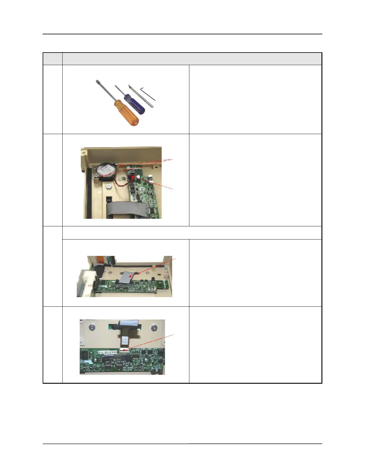
1 Tools/Supplies needed:
• Philips Head Screwdriver, small point
• 5/16” Nut Driver
• 1/16” Ball Hex Driver
• X-Acto® Knife
• RTV- Zoll #s
• 602-0001-01(3oz)
• 602-0001-02(10oz)
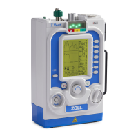
2 Buzzer - Kit#:712-0731-37
Remove two (2) 4-40 x
¼" Philips Pan Head screws that secure the Buzzer to
the Front
Pinch locking tab then remove the Buzzer's 2- Pin
connector located at the UIM Adapter Printed Circuit
Board (PCB).
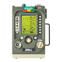
3 UIM Adapter, CPU w/Bracket and Pulse Oximeter PCB's
Disconnect the gray ribbon connector from the
Membrane Panel located at the UIM PCB by exerting
outward pressure on the ejector latches.
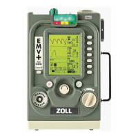
4 Disconnect the small ribbon cable beneath the gray
ribbon cable located at the UIM PCB by carefully
lifting its locking bar to release the cable.