Service Kit Installation Procedures
4–20 www.zoll.com 906-0731-04-01 Rev. C
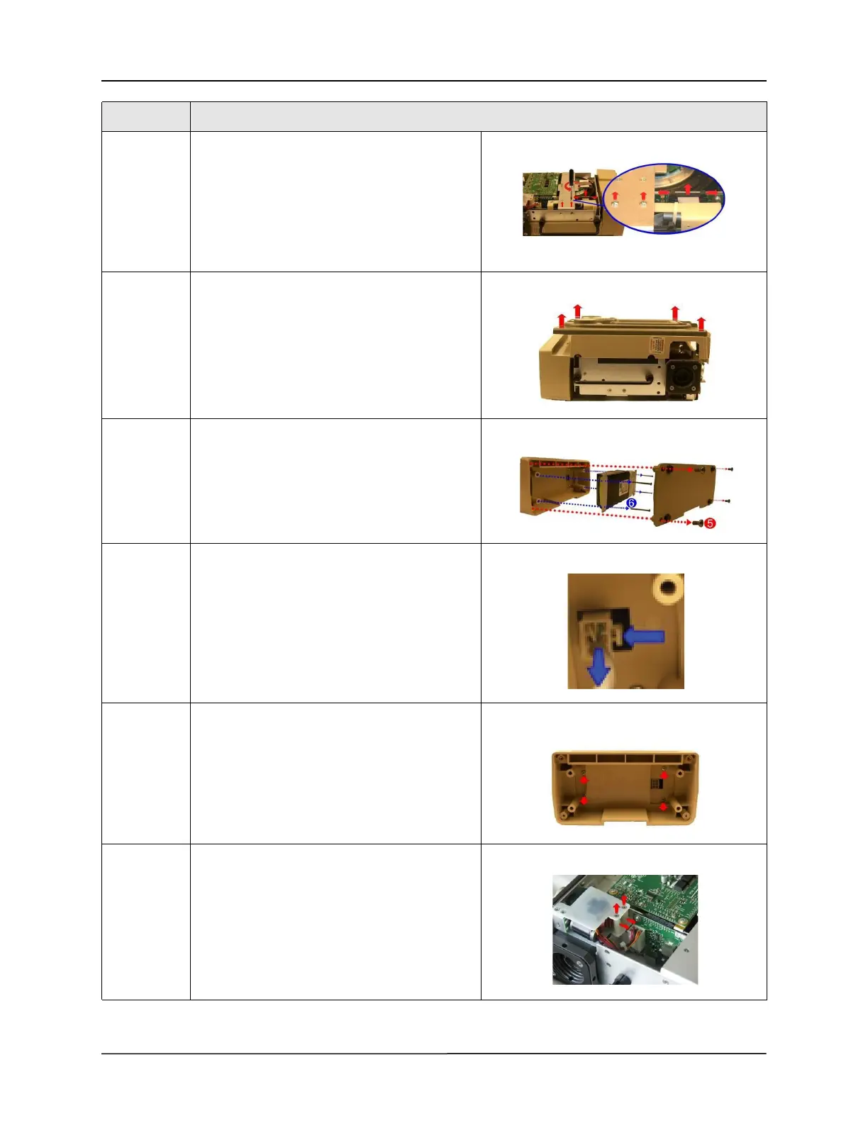
3 Remove the two Pan Head 4-40 x 1/4 screws on
the dovetail mounting bracket but do not
remove the two flat head screws. Disconnect the
ribbon cable on the Power Interface Module
(PIM) board by simultaneously applying pressure
on the two tabs.
Save these screws.
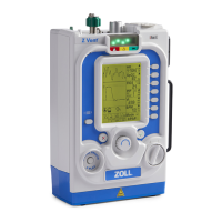
4 Flip the ventilator over and remove the front
case assembly by lifting it straight up away from
the ventilator module.
5 Remove the battery compartment cover by
unscrewing the four 6-32 x 5/16 screws.
Save these screws.
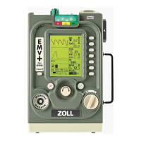
6 Remove the battery by unscrewing the four 6-32
x 2 1/4 screws and detaching the plug from its
locking latch.
Save these screws.
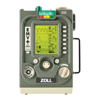
7 Unscrew the four 6-32 x 5/16 Phillips screws to
remove the battery compartment case.
Save these screws.
8 Loosen and remove the two 4-40 x 1 1/4 screws
and nylon spacers that support the Power Input
assembly within the chassis.
Save these screws and spacers.
Step Action