Service Kit Installation Procedures
906-0731-04-01 Rev. C ZOLL Ventilator Service Manual 4–31
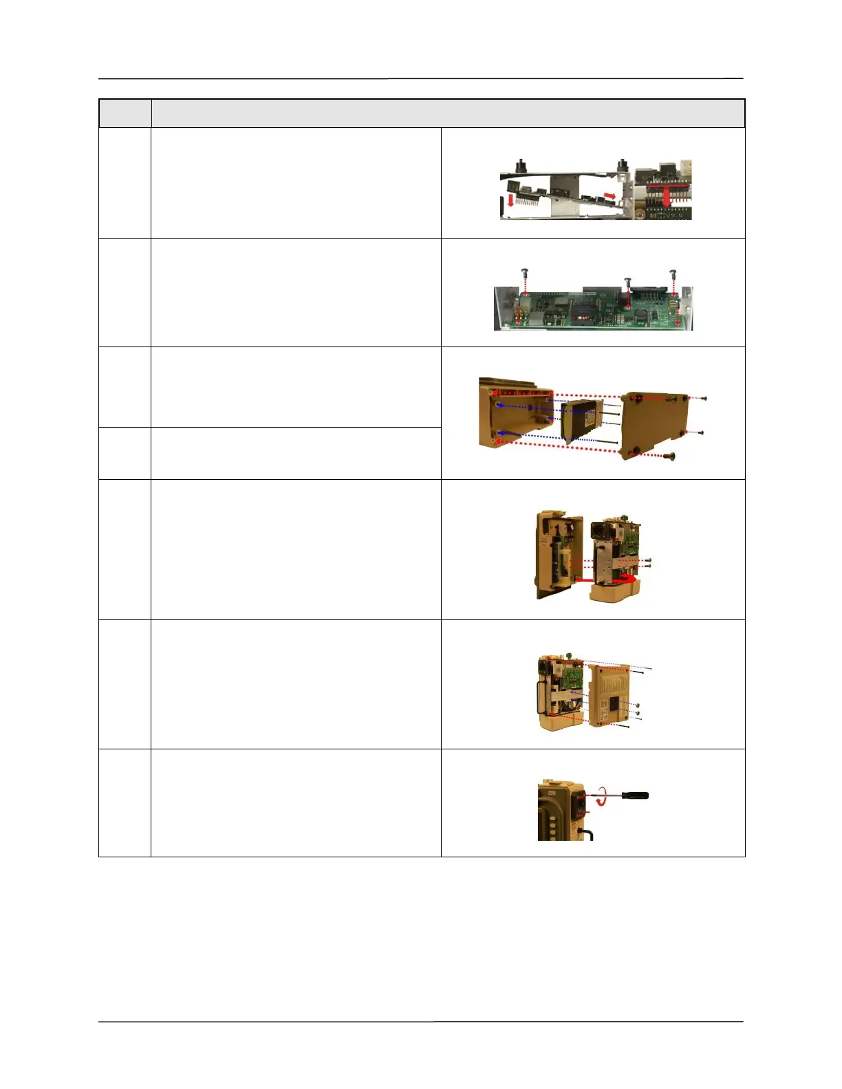
20 Reposition the PIM Board
Note: Make sure male header pins are inserted
correctly into the mating header.
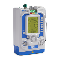
21 Secure the PIM board to the new SPM with the
five 4-40 x 1/4 screws. Caution: Do not over-
tighten the screws.
(Maximum torque - 3.5 in.- lb.)
22 Re-assemble the battery by connecting its cable to
the connector (pull lightly on the cable to ensure
it is locked in place) then tighten the four 6-32 x 2
1/4 screws.
23 Re-assemble the battery compartment cover by
tightening the four 6-32 x 5/16 screws.
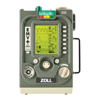
24 Place the front case assembly over the ventilator
module and tighten the two 4-40 x 1/4 screws to
the dovetail mounting bracket.
Reconnect the ribbon cable unto the PIM board.
Make sure the two ejector latches are secured.
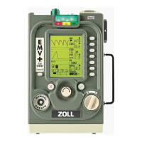
25 Attach the back case to the ventilator module and
align cover with handle, air intake housing and
dovetail mounting studs.
Insert and tighten the four 6-32 x 2” screws and
then the two 10-32 Keps nuts (provided in the kit).
26 Tighten the four 8-32 x 3 screws on the outer air
intake.
Step Procedure