Service Kit Installation Procedures
4–30 www.zoll.com 906-0731-04-01 Rev. C
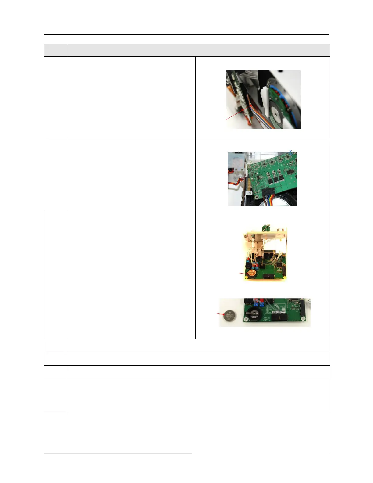
13 Remove the compressor cable from the bottom of
the SPM PCB by pressing the locking tab and
pulling the cable away from the board
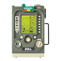
14 Carefully rotate the SPM PCB until the RTC battery
extends past the chassis.
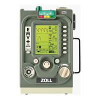
15 Remove the RTC battery, reload the tension on the
holding clip on the battery holder and insert the
new RTC battery.
16 Reconnect the Compressor cable to the SPM PCB and verify that it is locked in place.
17 Reattach the 4 screws 4-40 x ¼" screws holding the SPM PCB to the SPM.
18 Reattach the corrugated hose to the Compressor Air Intake base and the compressor intake port.
19 Reattach the Dovetail Mounting Bracket using the 4 6-32 x 1/4" flathead screws on the ends and 2 4-40 x
¼" flathead located towards the middle of the bracket.
Caution: Make sure to insert the SPO
2
insulator between the chassis and Dovetail Support bracket.
Step Procedure