Service Kit Installation Procedures
4–36 www.zoll.com 906-0731-04-01 Rev. C
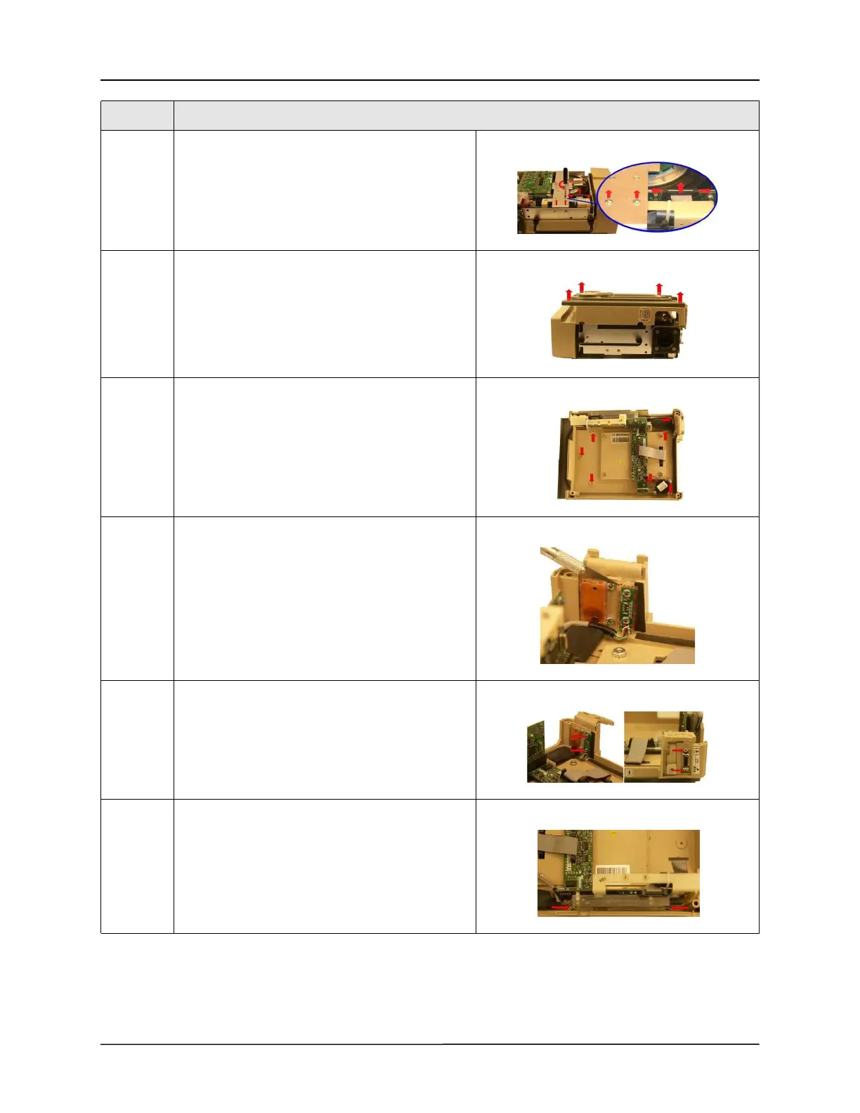
3 Remove the two 4-40 x 1/4 screws on the dovetail
mounting bracket, then disconnect the ribbon
cable on the PIM board by simultaneously applying
pressure on the two ejector latches.
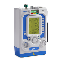
4 Flip the ventilator over and remove the front case
assembly by lifting it straight up away from the
ventilator module.
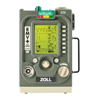
5 Remove the bezel by loosening and removing the
seven 4-40 x 1/4 screws that hold the bezel to the
front case.
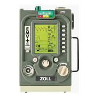
6 Using a sharp knife, carefully cut the RTV sealant
around the USB Printed Circuit Board and around
the SpO
2
Connector.
Note: Take precaution not to cut either cable.
7 Loosen and remove the two 4-40 x 3/16 screws
holding the Mini USB Cable Assembly to the front
case.
Loosen and remove the two M2.5 x 5mm screws
holding the SpO
2
cable to the front case.
8 Loosen and remove the two 6-32 x 5/16 screws that
hold the CPU/UIM & SpO
2
Stack to the front case.
Step Action