Service Kit Installation Procedures
906-0731-04-01 Rev. C ZOLL Ventilator Service Manual 4–37
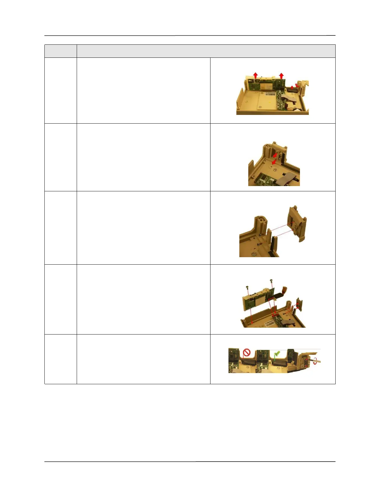
9 Lift the CPU/UIM & SpO
2
Stack up from the front
case. Handle the SpO
2
cable with extreme care. Do
not pull on the cable.
10 Loosen and remove the two 4-40 x 5/16 screws
holding the damaged USB Connector Plate to the
front case.
11 Insert and tighten the two 4-40 x 5/16 screws
(provided in the kit) while holding the replacement
USB Connector Plate to the front case.
12 Tighten the two 6-32 x 5/16 screws that hold the
CPU/UIM & SpO
2
Stack to the front case. Make
sure that all the pins on the header mate correctly.
13 Make sure the SpO
2
Flex Cable lays flat against the
front case and is assembled correctly into the UIM
Bracket and SpO
2
Isolation Shield.
Insert and tighten the two M2.5 x 5mm screws
holding the SpO
2
cable to the front case.
Step Action