EasyManuals Logo

2N Helios IP User Manual

2N Helios IP
119 pages
To Next Page IconTo Next Page
To Previous Page IconTo Previous Page
Page #38 background imageLoading...
Page #38 background image
Extending Module Connection
2.5
38
Module Cable Interconnection
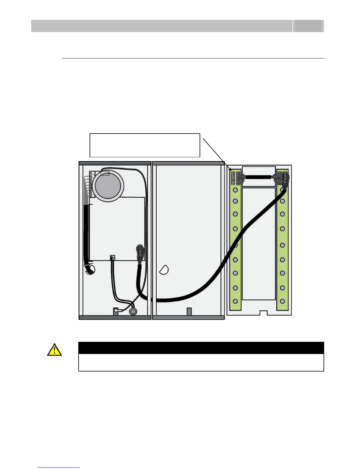
The cable is included in every extending module delivery. Both its ends are
the same. Configuration is 1:1. Connectors cannot be shifted or inserted
conversely because they are equipped with a so-called key.
The basic unit is always on the left. Extenders are chain-connected, i.e. each
is linked with its neighbour.
The cable cannot be driven through the box interconnecting holes until the
boxes have been connected (see subsection 2.3 Mounting Mechanical
Installation).
Figure 2.16 Connection of Two-Button-Row Extending Module
Caution
The extending modules must be connected mutually and with the basic
unit by means of a formed piece supplied with the extending module!!!
This connector is designed for
interconnection.

Table of Contents

Other manuals for 2N Helios IP

Questions and Answers:

Question and Answer IconNeed help?

Do you have a question about the 2N Helios IP and is the answer not in the manual?

2N Helios IP Specifications

General IconGeneral
TypeIP Intercom
ConnectivityEthernet
Tamper SwitchYes
AudioFull duplex
MicrophoneBuilt-in
SpeakerBuilt-in
CameraYes
Power SupplyPoE
Operating Temperature+60°C
Ingress ProtectionIP54
ProtocolsSIP, RTSP, ONVIF
Audio CodecG.711, G.722
InstallationSurface mount, flush mount (depending on model)

Related product manuals