Mounting – Electrical Installation
31
Caution
Make sure that the cables leading through the 2N
®
Helios IP cover bottom
groove are installed properly. For the correct installation of the cables
refer to Figure 2.7.
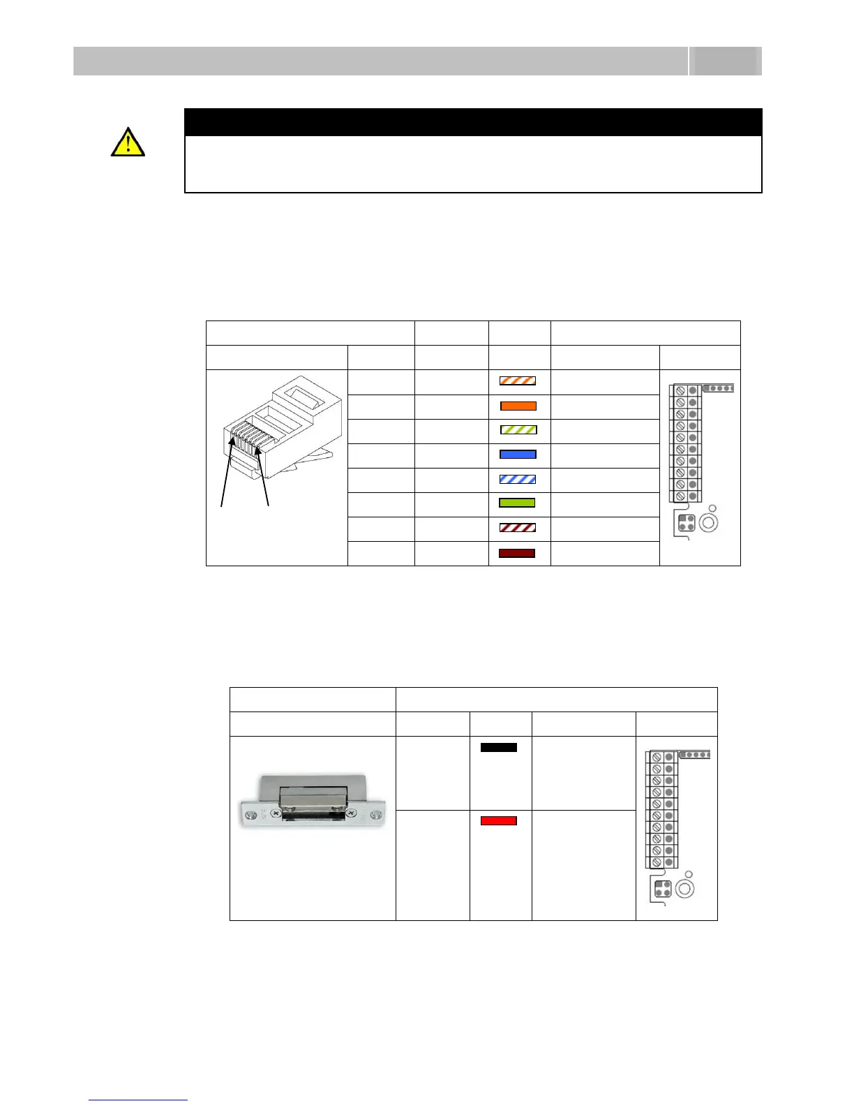
Ethernet Connection
For the connections and meanings of the wires see the table below. Join UTP cable
wires 4 (blue) and 5 (white-blue) and attach them under terminal 7 on 2N
®
Helios IP.
In the same way, join wires 7 and 8 and place them under terminal 5 of 2N
®
Helios IP.
Table 2.1 Terminal Block Connections
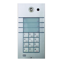
Electric Lock Connection
The electric lock can be connected to terminals 3 and 4 of terminal block X2.
Table 2.2 Terminal Block Connection for Electric Lock
Terminals 3 and 4 are connected to a relay on the 2N
®
Helios IP board. The relay
terminals may act as normally open or normally closed contacts. Configuration is
performed through the configuration connector X1 as described in the