EasyManuals Logo

2N Helios IP User Manual

2N Helios IP
119 pages
To Next Page IconTo Next Page
To Previous Page IconTo Previous Page
Page #37 background imageLoading...
Page #37 background image
Extending Module Connection
2.5
37
2.5 Extending Module Connection
2N
®
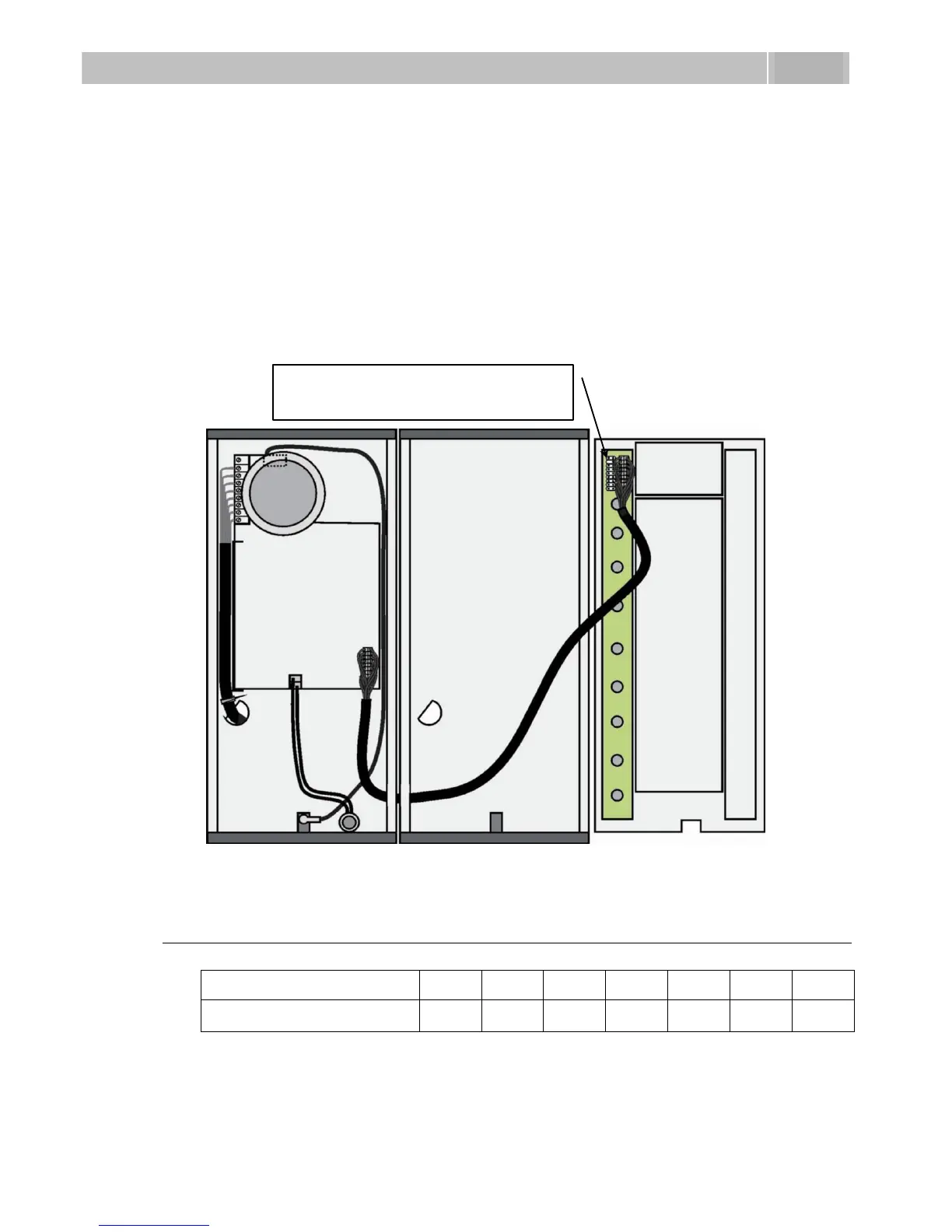
Helios IP features an easy installation of extending button modules. Extending
modules are connected using a single cable (included in every extender delivery) in a
chain pattern (every additional unit is connected with the previous one). Each
extending module has two connectors an input connector (for connection towards
the 2N
®
Helios IP basic unit) and an output connector (for connection of another,
more remote unit). Be sure to maintain the correct orientation of the units and avoid
connector mismatch to ensure a proper function of the device!
Figure 2.15 Connection of One-Row-Button Extending Modules
Maximum Count of Extenders
9135181E (1×8 buttons)
6
5
4
3
2
1
0
9135182E (2×8 buttons)
0
0
1
1
2
2
3
Table 2.6 Optional 2N
®
Helios IP Extension
The table above shows how to combine modules with single (whole) and double
buttons.
This connector is designed for an
additional extending module.

Table of Contents

Other manuals for 2N Helios IP

Questions and Answers:

Question and Answer IconNeed help?

Do you have a question about the 2N Helios IP and is the answer not in the manual?

2N Helios IP Specifications

General IconGeneral
TypeIP Intercom
ConnectivityEthernet
Tamper SwitchYes
AudioFull duplex
MicrophoneBuilt-in
SpeakerBuilt-in
CameraYes
Power SupplyPoE
Operating Temperature+60°C
Ingress ProtectionIP54
ProtocolsSIP, RTSP, ONVIF
Audio CodecG.711, G.722
InstallationSurface mount, flush mount (depending on model)

Related product manuals