963D SYSTEMS, INC.
6. Make sure the airlock is in OPEN position, then put the calibration plate on the airlock.
7. Rotate the airlock in CLOSE position.
8. Open the front door.
9. Put the glove and open the glove doors.
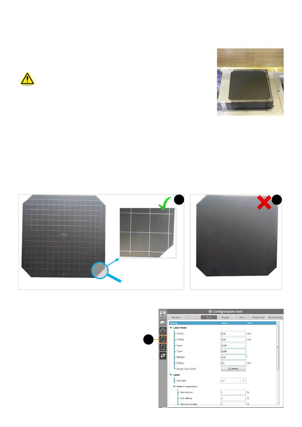
10. Install the sintering plate on the sintering piston.
Make sure the painted surface of the calibration plate is visible when
positioning it on the sintering piston, as showned on the adjacent gure.
11. Close the glove door.
12. Launch the inerting process up to reach the fume safety level.
13. Download the specic manufacturing FAB le on the printer.
14. Start the draw (layer#0) of the calibration plate with the red point in order to control its positioning. Adjust the
calibration plate it if is necessary.
15. Start the draw (layer#0) of the calibration plate without the red point.
16. Repeat the previous step, to be sure the draw will be well marked.
17. Move up the sintering piston about 5-10mm, for easier calibration plate removal.
18. Remove the calibration plate from the printer.
19. Inspect visually the sintered lines are homogeneously well marked over the whole surface of the plate (1). If the result is
not correct (2), repeat the draw on a new calibration plate. If the result is still no correct, contact 3D Systems Customer
Support.
20. The control of the calibration requires the current correction le. To export this correction le:
• Access to the Conguration tool,
• Click on the Export button (1),
• Select "Correction le" from the le list, then save
the le on a folder from your network or a USB
key.
1
Calibration plate with crossing-lines homogeneously well marked
1
Calibration plate with crossing-lines
not marked correctly
2