Parameters 89
Abs output
frequency
01.63 Abs output frequency (page 70). 28
Abs motor torque 01.64 Abs motor torque (page 70). 30
Abs output power 01.65 Abs output power (page 70). 31
Abs motor shaft
power
01.68 Abs motor shaft power (page 70). 32
AO1 data storage 13.91 AO1 data storage (page 93). 37
AO2 data storage 13.92 AO2 data storage (page 93). 38
Other Source selection (see Terms and abbreviations on page 64). -
13.13 AO1 forced value Forced value that can be used instead of the selected output
signal. See parameter 13.02 AO force selection.
0.000 mA
0.000…22.000 mA /
0.000…11.000 V
Forced value for AO1. 1 = 1 unit
13.15 AO1 unit selection Selects the unit for readings and settings related to analog
input AO1.
Note:
In firmware ASCL2 and ASCL4), this setting must
match the corresponding hardware setting on the drive
control unit. See chapter Electrical installation, section
Switches in the Hardware manual of the drive and the default
control connections for the macro in use in chapter Control
macros (page 55). Control board reboot (either by cycling the
power or through parameter 96.08 Control board boot) is
required to validate any changes in the hardware settings.
mA
VVolts. 2
mA Milliamperes. 10
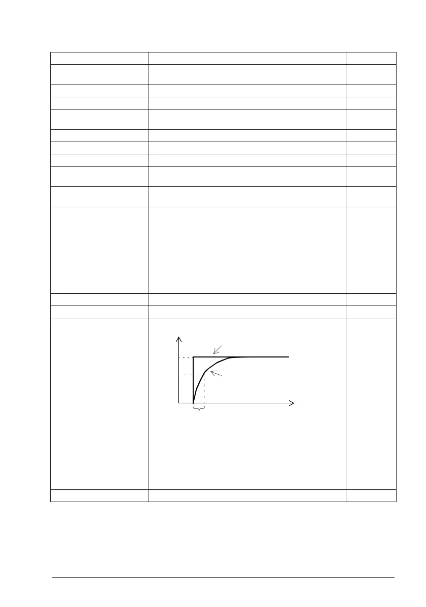
13.16 AO1 filter time Defines the filtering time constant for analog output AO1. 0.100 s
0.000 … 30.000 s Filter time constant. 1000 = 1 s
No. Name/Value Description Def/FbEq16
63
%
100
T
t
O = I × (1 - e
-t/T
)
I = filter input (step)
O = filter output
t = time
T = filter time constant
Unfiltered signal
Filtered signal
ACQ80 FW.book Page 89 Thursday, February 14, 2019 11:33 AM

 Loading...


