Operation principle and hardware description 33
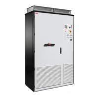
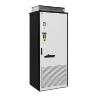
A Main breaker and power cabling cubicle
B Drive module cubicle
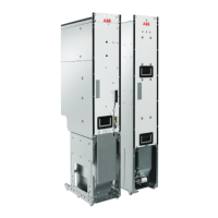
C Swing-out frame on the drive module side open
1 Main switch-disconnector (Q1) handle
2 Drive control panel (see page 40)
3 Operating buttons and door lights (see page 39)
4 Indicators, eg, V-meter and A-meter
5 UL Type V-meter
6 V-meter switch
7 Drive module
8 LCL filter module
9 Charging switch/contactor (Q3)
10 Drive module main cooling fans (1…2 pcs, 690 V R11 module has only one fan)
11 LCL filter module cooling fan
12 Circuit board fan

 Loading...


