Safety functions 63
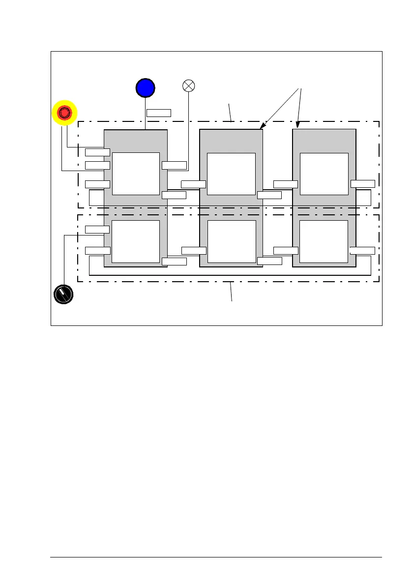
The inputs and outputs of the FSO module are defined as pairs. In this example,
single input X113:2 is cascaded with single output X113:8 in Cascade A. When
Emergency stop (Safety function 1 = SSE) is activated in the master FSO module
(from a redundant digital input X113:1 & X114:1), it is also activated in the follower
FSO modules via digital master FSO outputs. Safety function 2 is cascaded with
single input X113:3 and single output X113:9 (Cascade B). When POUS (Safety
function 2 = POUS) is activated in the master FSO module (from a single digital input
X113:4), it is also activated in the follower FSO modules. Feedback from the last FSO
in cascaded chain is wired back to master FSO.
You must configure one of the cascaded FSO modules as the master and the others
as followers.
You can configure a separate safety function indication both in the master and the
follower FSO modules. Use the completed output of the cascaded safety function for
the indication - in this example, output X113:7 is used to indicate SSE completed.
You must configure all follower FSO modules to use the automatic acknowledgement
method. The master FSO module can use any acknowledgement method. The
acknowledgement always starts from the master FSO module.
FSO
FSO
Safety
function
OutIn
Acknowledgement
button
Automatic
acknowledgement
FSO
FSO
Emergency
stop
G
E
M
E
R
E
N
C
Y
O
S
T
P
Follower
Follower
Safety
function
OutIn
Safety
function 2
OutIn
Safety
function
OutIn
Safety
function 2
OutIn
FSO
Master
Safety
function
OutIn
Safety
function 2
OutIn
X113:7
X113:1
X114:1
X113:2
X113:4
X113:2
X113:9
X113:3
X113:2
X113:8
X113:9
X114:2
X113:9
X113:3X113:3
POUS
switch
Cascade A
Cascade B
X113:8
X113:8
Safety
function 1
OutIn
OutIn
Safety
function
OutIn
Safety
function 1
OutIn
Safety
function
OutIn
Safety
function 1
OutIn
Indication lamp