Technical data 529
FSO safety calculations guide (with PROFIsafe)
Safety functions can also be implemented with PROFIsafe over PROFINET
connectivity. FSO has own subsystem for PROFIsafe communication which is used
together with other FSO internal subsystems.
PROFIsafe can replace digital inputs and/or digital outputs of the FSO. For example,
it is possible to use PROFIsafe input and FSO output in the same configuration.
It is also possible to read and activate FSO I/O’s through the PROFIsafe connection.
In this case, the safety block diagram must contain either the FSO input or the FSO
output subsystem.
It is also possible that customer's PLC uses safe position information to operate a
safety function. In this case, FSE-31 subsystem should be added in the calculation.
Safety data for some typical configurations
The tables below show FSO-21 safety data for some safety functions with typical
combinations of the FSO module subsystems. See section Basic safety data on
page 522 for more information on the subsystems.
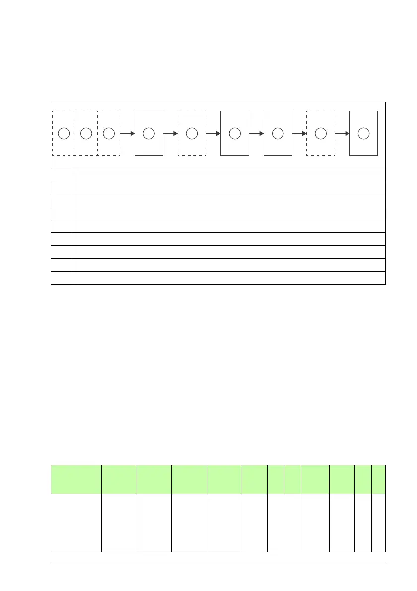
Values without the FSE-31 module
1 Input
2 PLC Logic
3 Output
4PROFIsafe
5 FSO Digital input (optional)
6 FSO Logic (1 or 2)
7 FSO STO output
8 FSO Digital output (optional)
9Drive STO
Subsystems
used in the
safety function
PFH
(1/h)
PFD
avg
PFD
avg
PFD
avg
SFF
1)
HFT SIL MTTF
D
DC
2)
Cat. PL
(T1 = 20 a) (T1 = 2 a) (T1 = 5 a) (T1 = 20 a) (%) (a) (%)
1-channel
pulsed DI
Logic
STO-output
1-channel
pulsed output
Speed estimate
1.1E-08 1.4E-04 2.7E-04 5.0E-04 99.0 0 2 149 98.7 2 d