192 Safety functions
SDI trip limit hits
This applies to SDI trip limit hit situations, that is, when the motor rotates too much to
the forbidden direction while the SDI monitoring is on. The SDI positive function is
used as an example.
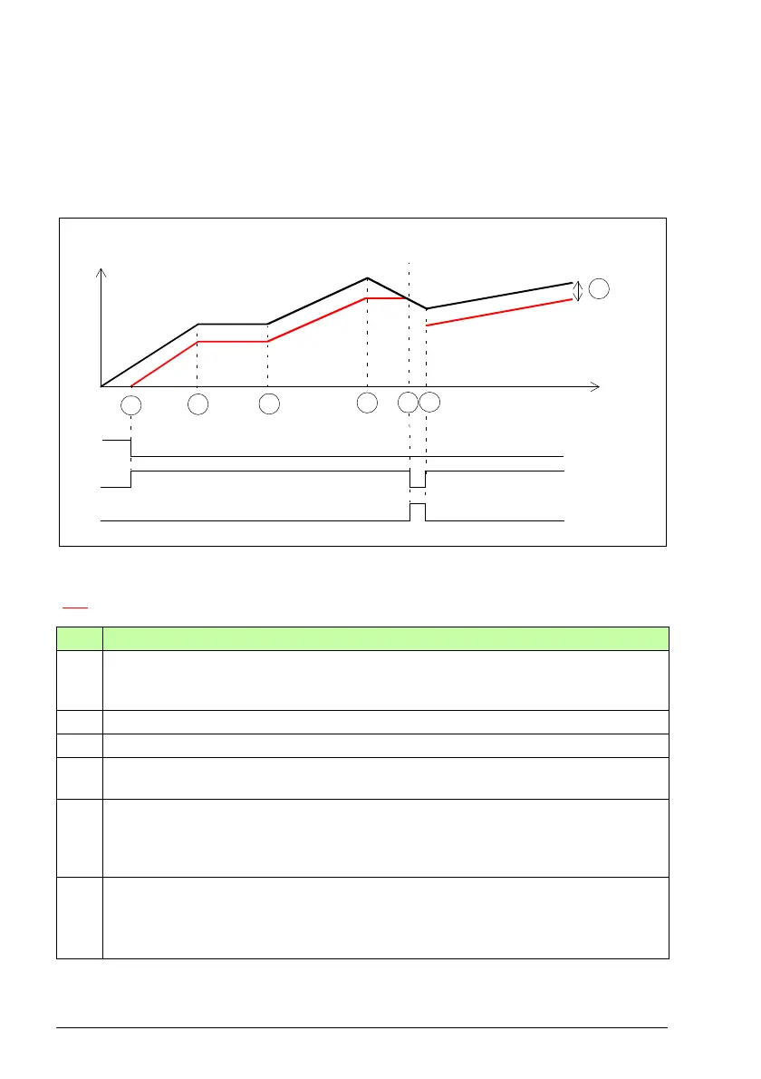
Note: This diagram shows the position of the motor shaft (not the motor speed).
A SDI tolerance limit degree (parameter SDI.14): The motor shaft cannot move to the
forbidden direction more than defined with this parameter.
SDI monitoring limit
Step Description
1 The SDI positive request is received (for example, from the I/O) and the FSO starts the
SDI monitoring. The SDI active indication goes on. The motor rotates to the correct
direction (in this case, positive).
2 The motor stops.
3 The motor starts to rotate again (into the positive direction).
4 The rotation direction of the motor changes to the forbidden (negative) direction. The
FSO locks the SDI tolerance limit (A) into its current position.
5 The SDI tolerance limit (A) is reached. The FSO stops the SDI monitoring and activates
the SSE function and the motor coasts to a stop. The SDI indication goes off. The SSE
indication goes on. See section Safe stop emergency (SSE) on page 106 for more
information on how to configure the SSE function.
6 The motor has stopped. The SSE function is completed and the FSO starts the SDI
monitoring. The SDI active indication goes on and the SSE indication goes off.
When the motor starts to rotate again (into the correct direction), the SDI monitoring
continues with the original SDI tolerance limit (A).
SDI state &
indication
SDI request
Motor shaft
position
Time
1
2
4
SSE state &
indication
A
3
5
6
- -> Safe stop emergency (SSE)