524 Technical data
FSO safety calculations guide (without PROFIsafe)
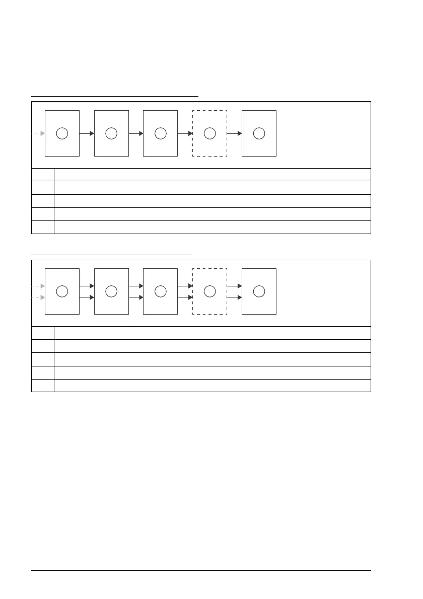
STO, SS1-t, SSE-t and SSE with immediate STO
Block diagram for single channel solution:
Block diagram for dual channel solution:
STO and other stopping functions with FSO include FSO subsystems Digital input,
Logic, possible Digital output and STO output, and Drive STO. In the figure above,
safety function is implemented with 1-channel and non-pulsed signals which requires
Logic 1. Figure 2 shows a 2-channel solution. Signals may be either pulsed or non-
pulsed, thus Logic 2 is used. However, all choices have an effect on safety values. In
general, if the safety function contains any 1-channel digital input or output of the
FSO with non-pulsed signals, the subsystem "Logic 1" must be used. Block diagrams
are equal to SS1-t, SSE-t and SSE with immediate STO functions. Same approach
for the logic subsystems applies in all safety functions below.
Note: ABB's safety data component libraries do not contain any subsystems for
external (non-ABB) components.
Note: All safety functions in FSO can be activated either through safety IOs or
through PROFIsafe. In case PROFIsafe is used, safety IOs are optional.
1 FSO Digital input
2 FSO Logic 1
3 FSO STO output
4 FSO Digital output (optional)
5Drive STO
1 FSO Digital input
2 FSO Logic 2
3 FSO STO output
4 FSO Digital output (optional)
5Drive STO