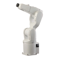
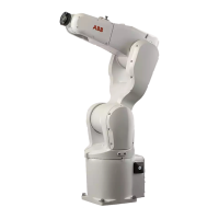
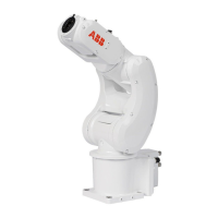
xx0900000643
Level surface requirements
Orienting and securing the robot
Use this procedure to orient and secure the robot.
InformationAction
Make sure the installation site for the robot con-
forms to the specifications in section:
• Pre-installation procedure on page 56.
1
The hole configuration of the base
is shown in the figure in:
• Hole configuration, base on
page 70
Prepare the installation site with attachment
holes.
2
CAUTION
The robot weighs 25 kg. All lifting equipment
must be sized accordingly!
3
CAUTION
When the robot is put down after being lifted or
transported, there is a risk of it tipping, if not
properly secured.
4
How to lift the robot is described in
section:
• Lifting the robot with round-
slings on page 63
Lift the robot to its installation site.5
2 pcs, D6x20Fit two pins to the holes in the base.6
ISO 2338-6 m6x30 - A1
Make sure the robot base is cor-
rectly fitted onto the pins.
Guide the robot gently, using the attachment
screws while lowering it into its mounting posi-
tion.
7
Screws: M10x25, quality: 8.8-A3FFit the securing screws and washers in the attach-
ment holes of the base.
8
Tightening torque:Tighten the bolts in a criss-cross pattern to en-
sure that the base is not distorted.
9
35 Nm
Securing robot on a mounting plate
When bolting a mounting plate or frame to a concrete floor, follow the general
instructions for expansion-shell bolts.
Screw joints must be able to withstand the stress loads defined in section Loads
on foundation, robot on page 57.
Product manual - IRB 120 71
3HAC035728-001 Revision: N
© Copyright 2009-2017 ABB. All rights reserved.
2 Installation and commissioning
2.3.3 Orienting and securing the robot
Continued
 Loading...


