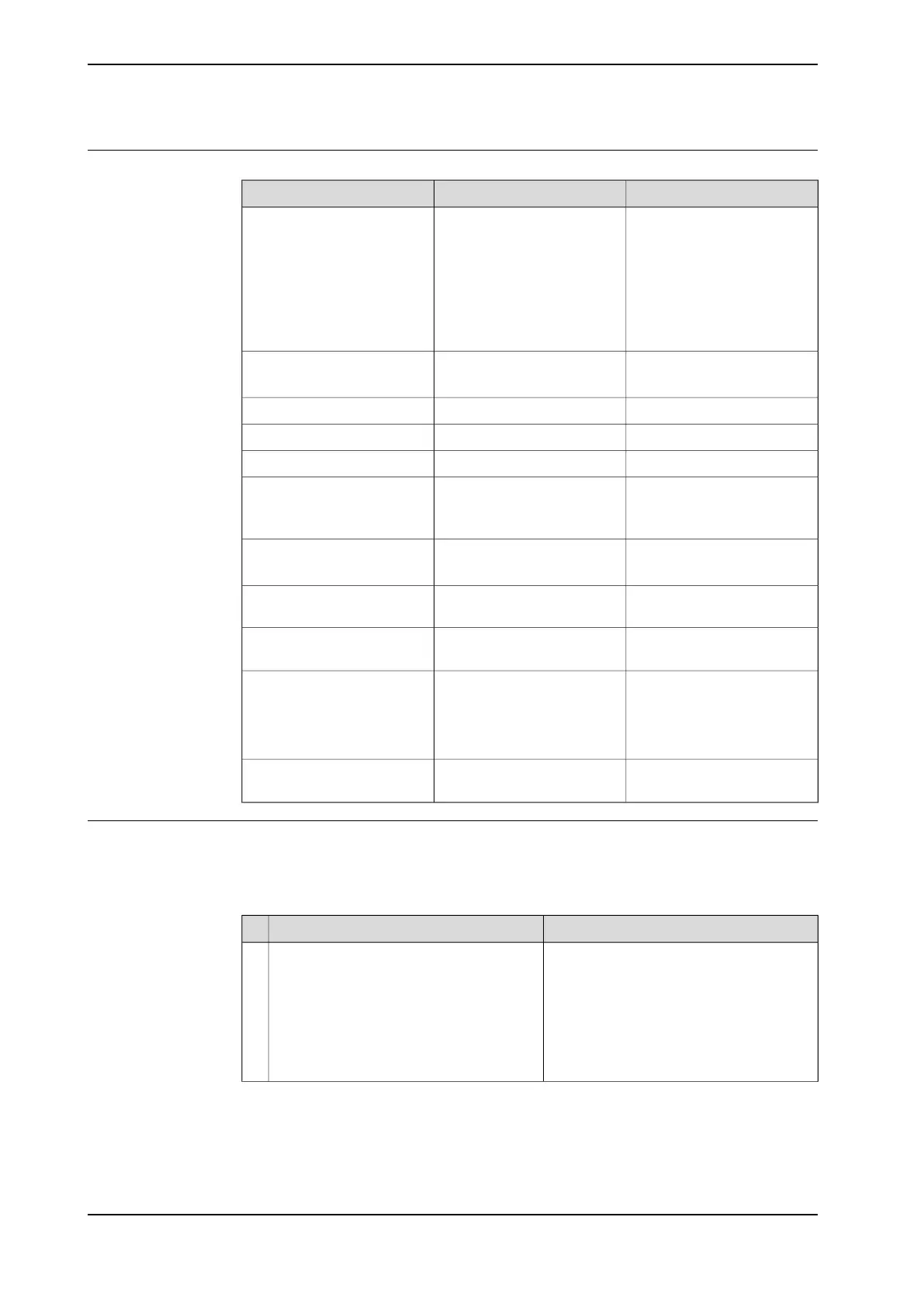
Required equipment
NoteArt. no.Equipment, etc.
Used to guide the complete
arm system when refitting.
3HAC022637-001Guide pins M12 x 130
Always use the guide pins in
pairs!
Guide pins that are longer
than 140 mm will not be pos-
sible to remove because the
lack of space.
4 pcs.Roundsling
Lifting capacity 1,000 kg
3HAC040381-001Adapter
3HAC025333-005Lifting eye, M12
Lifting capacity: 1,000 kg.-Shackle
Stahlwille 736/40 D10 (or
similar)
-Bits holder
Used on the M12x140 screws.
24 VDC, max. 1.5 A-Power supply
For releasing the brakes.
Used to turn the gear when
mating it to the frame.
-Crank
Content is defined in section
Standard tools on page 383.
-Standard toolkit
These procedures include
references to the tools re-
quired.
Other tools and procedures
may be required. See refer-
ences to these procedures in
the step-by-step instructions
below.
See chapter Circuit diagrams
on page 391.
-Circuit diagram
Deciding calibration routine
Decide which calibration routine to be used, based on the information in the table.
Depending on which routine is chosen, action might be required prior to beginning
the repair work of the robot, see the table.
NoteAction
Decide which calibration routine to use for
calibrating the robot.
• Reference calibration. External cable
packages (DressPack) and tools can
stay fitted on the robot.
• Fine calibration. All external cable
packages (DressPack) and tools
must be removed from the robot.
1
Continues on next page
174 Product manual - IRB 460
3HAC039842-001 Revision: P
© Copyright 2012-2018 ABB. All rights reserved.
4 Repair
4.3.5 Replacing the base, including axis 1 gearbox
Continued

 Loading...


