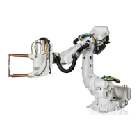
Securing the upper arm - IRB 6700 - 200/2.60, IRB 6700 - 155/2.85
NoteAction
CAUTION
The weight of the complete upper arm (in-
cluding the wrist) is
360 kg (IRB 6700 -235/2.65, -205/2.80, -
175/3.05, -150/3.20, -200/2.60, -155/2.85)
465 kg (IRB 6700 -300/2.70, -245/3.00)
All lifting accessories used must be sized
accordingly.
1
See Attaching lifting accessories to the
upper arm on page 228.
Attach the lifting accessories, if not already
fitted.
2
Lift the upper arm and put it on the guide
pins.
3
24 VDC power supplyIf the axis-3 motor is installed to the upper
arm:
4
Rotation tool
In order to release the brakes, connect the
24 VDC power supply.
Connect to R2.MP3-connector:
• + = pin 2
• - = pin 5
Use the rotation tool and rotate the axis-3
motor to find the correct position for the
guide pins in the lower arm.
Pinion:If the axis-3 motor is not installed to the
upper arm:
5
3HAC067546-001
i
Use the pinion to rotate the axis-3 gearbox
to find the correct position for the guide
pins in the lower arm.
3HAC067547-001
ii
3HAC067545-001
iii
xx1300002246
Insert 22 of the 24 M12 screws and wash-
ers.
6
Continues on next page
416 Product manual - IRB 6700
3HAC044266-001 Revision: N
© Copyright 2013 - 2018 ABB. All rights reserved.
4 Repair
4.5.5 Replacing the lower arm
Continued

 Loading...