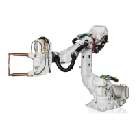
Holes for fitting extra equipment
Position of attachment holes - drawing 1
0,3
80
160
3x M10
A
A
(2x M12)
(2x M12)
C
L
Axis 5
2x M8
16
80
40
100
C
L
Axis 3
4x M12 22
220
190
110
90
328
192x M12
197
M12 19
22)
106 (4x M12
53
5
2
,
5
°
117R
1
3
4
x
M
8
M12 20
5
2
,
5
°
H
H
(150)
(150)
(109)
J
K
K
A - A
J
(2x M12
19)
(M12
19)
C
L
Axis 4
B
B
A
B
E
L
H
J
M
K
C
D
F
G
12
N
B - B
xx1300000263
Allowed position for attachment holes, M12 through. Be careful not to touch the cables when drilling.A
Continues on next page
Product manual - IRB 6700 91
3HAC044266-001 Revision: N
© Copyright 2013 - 2018 ABB. All rights reserved.
2 Installation and commissioning
2.4.8 Fitting equipment to the robot
Continued

 Loading...