4 Repair
4.5.2. Replacement of brake release unit
3HAC022033-001 Revision: K304
© Copyright 2004-2011 ABB. All rights reserved.
2.
esd
WARNING!
The unit is sensitive to ESD. Before
handling the unit please read the safety
information in the section WARNING - The
unit is sensitive to ESD! on page 49
3. Remove the push button guard from the
SMB cover.
Shown in the figure Location of brake
release unit, frame on page 302.
The guard must be removed to ensure a
correct refitting of the brake release unit.
4. Remove the SMB cover by unscrewing the
attachment screws.
Let the battery stay connected, to avoid the
need of synchronization of the robot!
Shown in the figure Location of brake
release unit, frame on page 302.
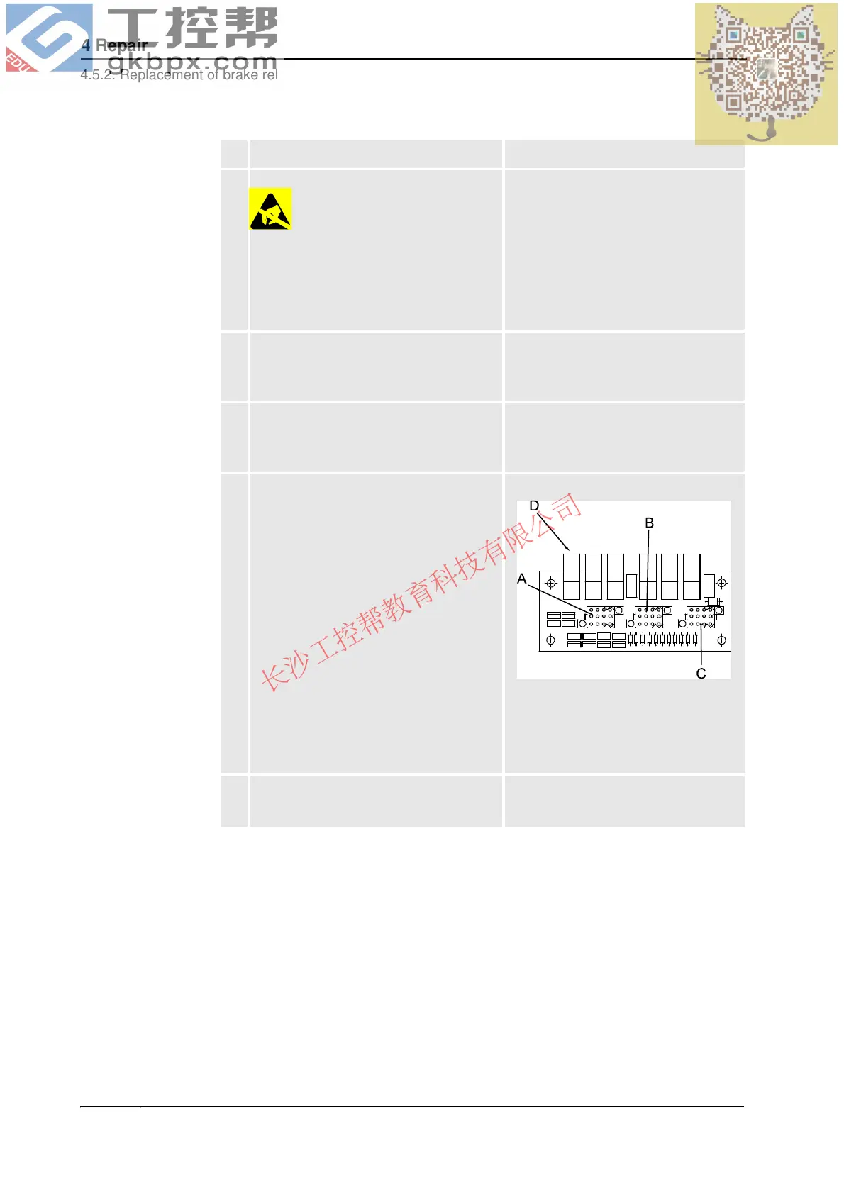
5. Disconnect the connectors X8, X9 and X10
from the brake release unit.
xx0200000129
• A: Connector X8
• B: Connector X9
• C: Connector X10
• D: Push buttons for each axis
6. Remove the brake release unit from the
plate by unscrewing the four attachment
screws, brake release unit.
Shown in the figure Location of brake
release unit, frame on page 302!
Action Note
Continued
Continues on next page
 Loading...


