4 Repair
4.7.3. Replacement of gearbox, axis 3
3HAC022033-001 Revision: K384
© Copyright 2004-2011 ABB. All rights reserved.
4.
CAUTION!
The gearbox weighs 125 kg! All
lifting equipment used must be
sized accordingly!
5. Fit the lifting eye to the gearbox. Art. no. is specified in Required equipment on page
381.
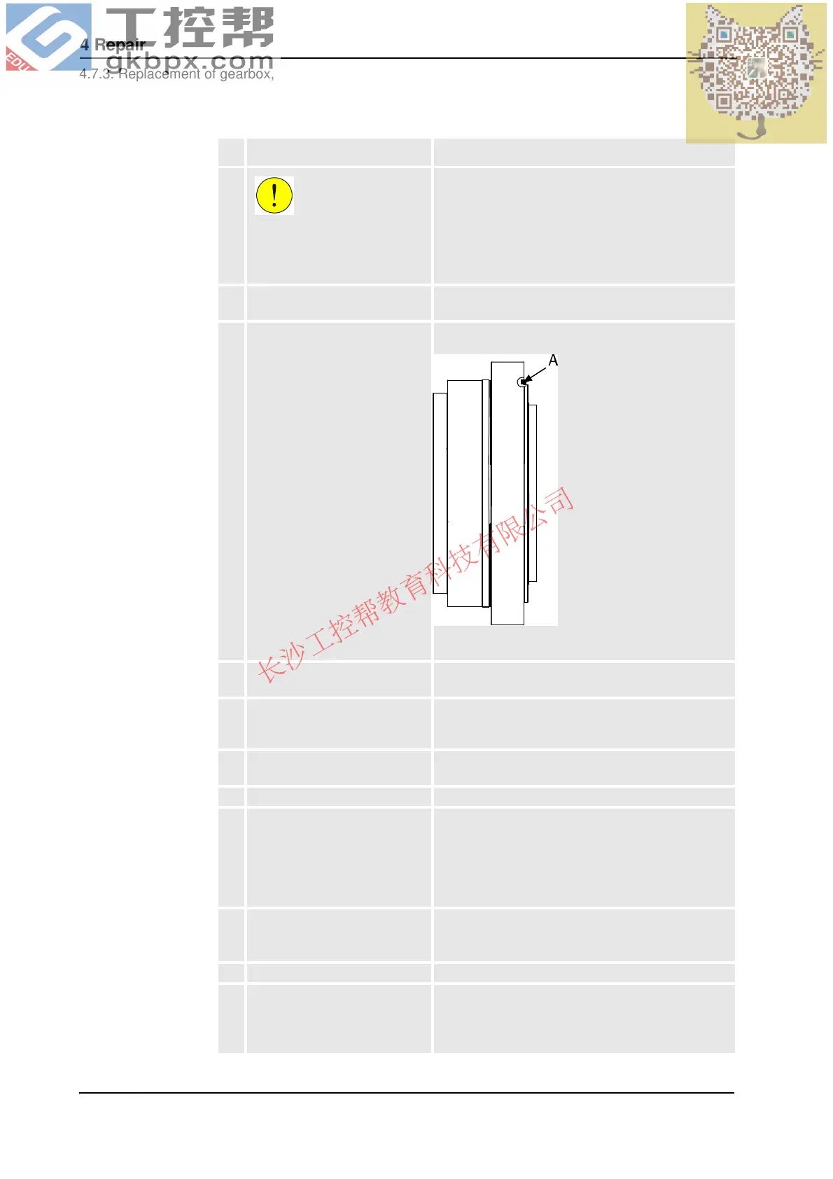
6. Make sure the o-ring is fitted to
the rear of the gearbox. Apply
grease to it to make sure it sticks
in its groove during assembly!
Replace if damaged!
Art. no. is specified in Required equipment on page
381.
xx0100000136
• A: O-ring, gearbox axis 3
7. Lift the gearbox to its mounting
position.
8. Turn the gearbox to align the
attachment screw holes with
those in the upper arm.
9. Fit the gearbox onto the guide
pins and slide it into position.
Make sure the o-rings are seated properly and the
gearbox correctly oriented!
10. Remove the lifting tool.
11. Secure the gearbox with 18 of
the 20 gearbox attachment
screws.
Remove the guide pins and
tighten the remaining two
screws.
20 pcs: M16 x 90; 12.9 quality UNBRAKO, tightening
torque: 300 Nm.
Reused screws may be used, providing they are
lubricated as detailed in section Screw joints on page
423 before fitting.
12. Refit the upper arm with a new
sealing, axis 2/3 .
Art. no. is specified in Required equipment on page
381.
Detailed in section Refitting, upper arm on page 285.
13. Refit the motor. Detailed in section Refitting, motor on page 344.
14. Recalibrate the robot! Calibration is detailed in a separate calibration
manual enclosed with the calibration tools.
General calibration information is included in section
Calibration information on page 403.
Action Note
Continued
Continues on next page