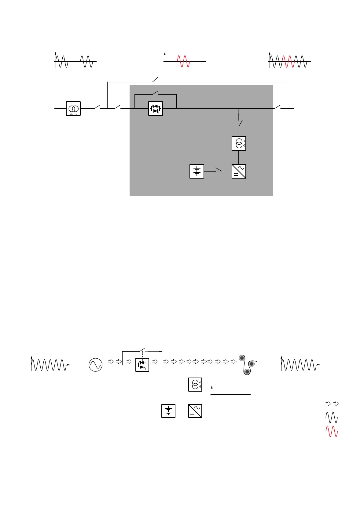
Figure 2-2: PCS100 UPS-I Single line diagram
2.3 Operation
The following diagrams show how the PCS100 UPS-I behaves when a utility disturbance occurs, and what
happens when the Fail-Safe Bypass is operating.
Note: The following diagrams show a Fail-Safe Bypass. In some PCS100 UPS-I models the Fail-Safe
Bypass is integrated and for other models it is optional.
2.3.1 Utility Voltage within Limits
The power to the load is supplied from the utility (Online mode). Inverters are idling and maintain synchronization
with the utility voltage to allow instant operation in the case of a utility disturbance. A Float Charger (not shown)
maintains the state of charge of the battery or Ultracapacitor storage.