30 PCS100 UPS-I User Manual
—
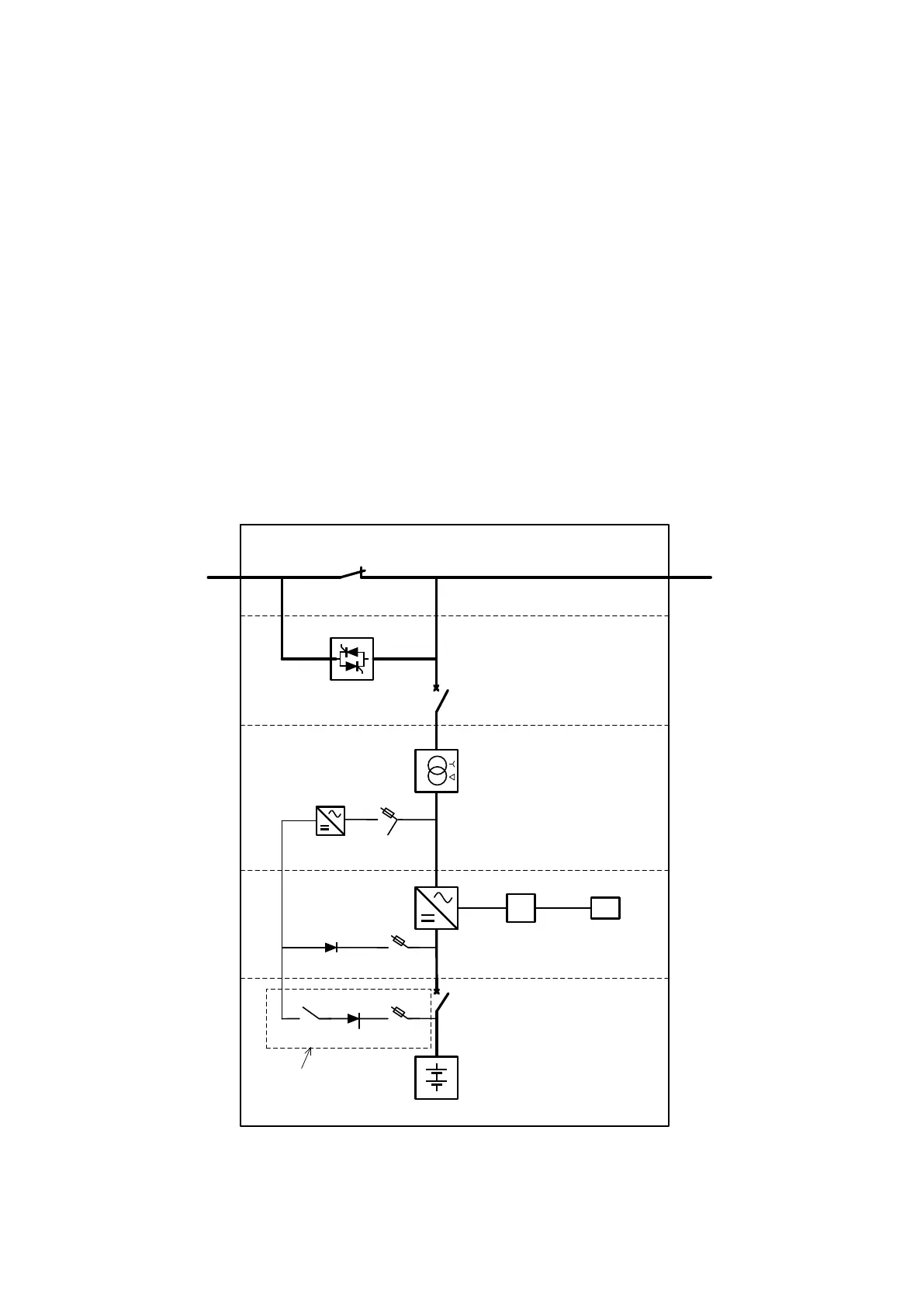
5 SUBASSEMBLIES
The PCS100 UPS-I consists of the following subassemblies:
– A Utility Disconnect that disconnects the utility supply during a disturbance
– Inverters that convert energy storage DC energy to 3-phase AC power
– Float Charger to charge the energy storage when the utility is operating normally
– A Fail-Safe Bypass to automatically bypass the PCS100 UPS-I when a fault occurs.
Note: The Fail-Safe Bypass is optional in some models.
– A Coupling Transformer to match the inverter output with the nominal utility voltage.
Note: There are two Coupling Transformers for 3 MVA systems.
– Energy Storage (Ultracapacitor or battery) that supplies power to the load during a utility
disturbance
Together, these sub-assemblies are referred to as the PCS100 UPS-I system. Small PCS100 UPS-I models have
multiple sub-assemblies in one enclosure. Large PCS100 UPS-I models may have one sub-assembly housed in
multiple enclosures.
Figure 5-1: PCS100 UPS-I SLD with enclosure definition
These sub-assemblies are described in the following sections.