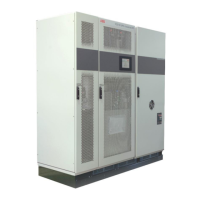
PCS100 UPS-I User Manual 35
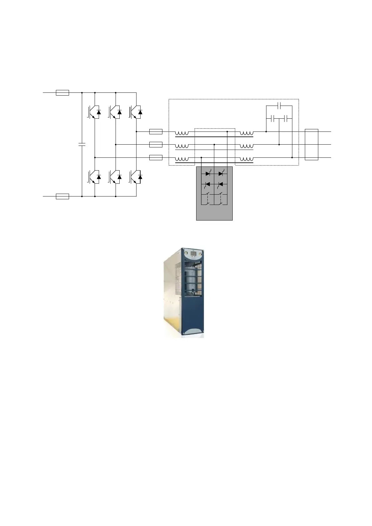
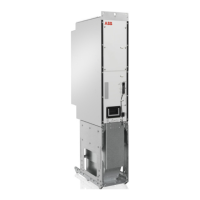
5.1.7 PCS100 Inverter
The PCS100 Inverter modules are IGBT based power electronics modules rated at 150 kVA.
The inverters include a sine filter as part of the assembly, meaning the power electronics and sine filter are
integrated into one module.
Figure 5-7: PCS100 UPS-I inverter diagram
Figure 5-8: PCS100 Inverter
In addition to converting DC storage voltage to AC voltage required by the load, the inverters quickly re-charge
the energy storage (fast charging) after a power quality event.
Depending on the required power, between one and twenty ABB PCS100 inverters are used.
Each inverter module has a unique identification number (1 - 32) which is displayed on the front of the module.
The inverter cooling fans are switched off most of the time. They switch on when the PCS100 UPS-I is discharging
and remain switched on for about 30 seconds afterwards.
The cooling air flow is 9 m
3
/min per inverter module.
Advanced Redundancy
The PCS100 UPS-I inverter consists of multiple 150 kVA PCS100 Inverter modules connected in parallel. If one
module fails the PCS100 UPS-I will automatically reconfigure during stand-by or while supporting the load to
operate with the remaining modules.
For example, a six inverter PCS100 UPS-I system offers 900 kVA for normal load protection. If one module fails,
the maximum system capacity will be reduced to 750 kVA, and the PCS100 UPS-I GDM (HMI) will indicate system
availability of 83%.
A maximum of 50% of the modules can fail before the PCS100 UPS-I will trip out.