54 PCS100 UPS-I User Manual
7.1.3 Status Bar
The status bar displays the PCS100 UPS-I status and any warning or fault code (if present).
Warning Condition
Fault or Warning
description
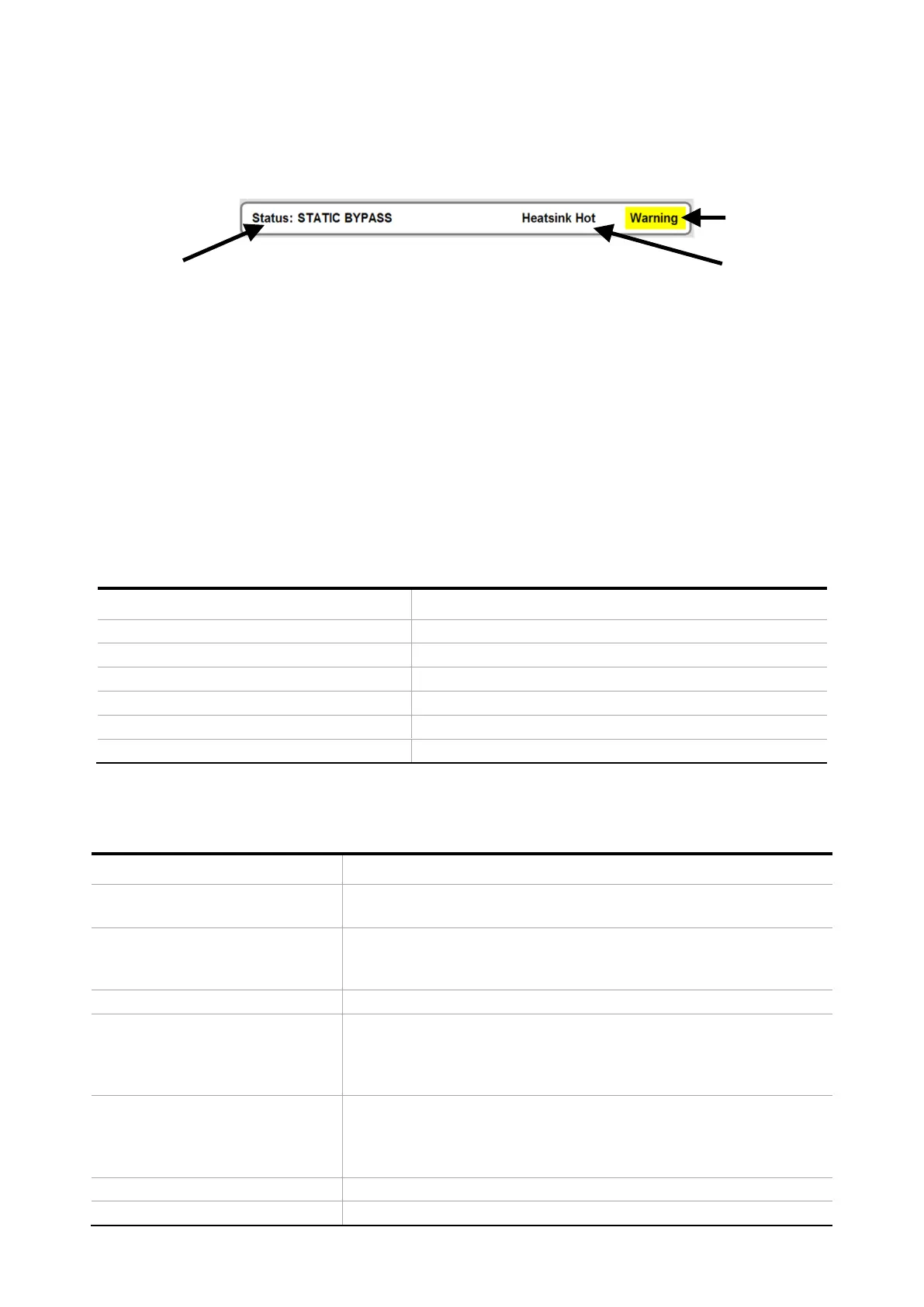
Figure 7-5: PCS100 UPS-I Status Bar example
1. PCS100 UPS-I Status. Refer to Table 7-4 for a complete list of status messages. See also Figure 7-6
2. Fault or Warning description. The event code number can be found in the event log. Refer to section 11 for
complete event descriptions.
3. “Warning” will be displayed if any warning condition exists.
Note:
The Status Bar will only display the most recent event or what is considered the most important event. Touch the
Status Bar and a list of all faults and warnings presently active will be displayed.
Color of status bar depends on PCS100 UPS-I status as shown in Table 7-3.
Run (Online, Discharging, etc.) with no warning
Green with yellow flashing warning cell
Run (Online, Discharging, etc.) with Warning present
White with yellow flashing warning cell
Static Bypass with Warning present
Starting – System Bypassed
Table 7-3: PCS100 UPS-I Status Bar Colors
Figure 7-6 shows the PCS100 UPS-I state flow diagram.
The PCS100 UPS-I is stopped: The Fail-Safe Bypass is closed. (See
Figure 7-4)
The PCS100 UPS-I is booting up or initializing or there is no
response from the master this could be due to the GDM CAN
cable disconnected.
The PCS100 UPS-I has tripped, or it is clearing a trip.
Starting – system bypassed
Waiting until the inverters start. The storage DC voltage must be
greater than 650VDC, PLL locked, FSB open and the utility voltage
within thresholds (parameters 530,531,533 and 535) for the UPS-I
to go Online.
Load is operating from the utility supply. The utility voltage and
frequency are within limits. The PCS100 UPS-I is ready to back up
the load in case the utility voltage or frequency goes beyond the
thresholds
The PCS100 UPS-I has returned to the utility supply. The PCS100