64 PCS100 UPS-I User Manual
7.3 PCS100 Inverter Display Boards
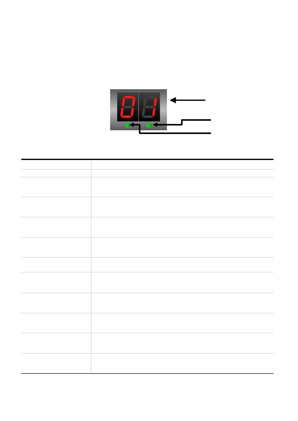
The PCS100 Inverter modules contain their own display boards which contain the RUN and OK LEDS, as well as 2 x
7 segment LED displays.
The 7 segment displays show the individual module identification number (1 – 32), however if there is an error
condition they will flash alternately every 500 ms the module identification number and an error code. On start-up
they will show L0 and L1 indicating the states in the start-up sequence.
7 segment LED display
OK LED
RUN LED
Figure 7-14: Module Status LEDs
Product Status or Description
“L0” and the module number
FLASH (50% duty, 1sec
period)
Booting.
This is normal just after power up.
“L1” and the module number
FLASH (50% duty, 1sec
period)
Configuring.
This is normal during start up after booting (L0) has completed.
“ou” and the module number
FLASH (50% duty, 1sec
period)
The module is running, and it has been configured as an inverter (output).
This is displayed for about 2 minutes after configuration (L1) is completed.
“E0” and the module number
FLASH (50% duty, 1sec
period)
A fault has occurred in the module.
See error message on GDM
The module is running.
This is displayed after configuration (L1) is completed.
“E1” and the module number
FLASH (50% duty, 1sec
period)
Problem starting the module – invalid parameter/s.
No communication with DSP (digital signal processor) in the master module.
Possible DSP hardware failure.
“E2” and the module number
FLASH (50% duty, 1sec
period)
Problem starting the module – invalid parameter/s.
“u0” and the module number
FLASH (50% duty, 1sec
period)
Requested operation mode: using internal dip switch setting.
“u1” and the module number
FLASH (50% duty, 1sec
period)
Requested operation mode: rectifier/input module (not applicable to
PCS100 UPS-I).
“u2” and the module number
FLASH (50% duty, 1sec
period)
Requested operation mode: inverter/output module.
Table 7-12: 7 segment LED displays