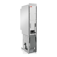
The Ultracapacitor module’s overvoltage and
overtemperature inputs are connected to the
Ultracapacitor Monitor Board in groups of 4,
representing 1 shelf in the enclosure. The upper and
lower strings are separated on the board and are
managed as separate entities, i.e. a faulted upper
string Ultracapacitor module will only trip the upper
string DC circuit breaker and DC charge switch.
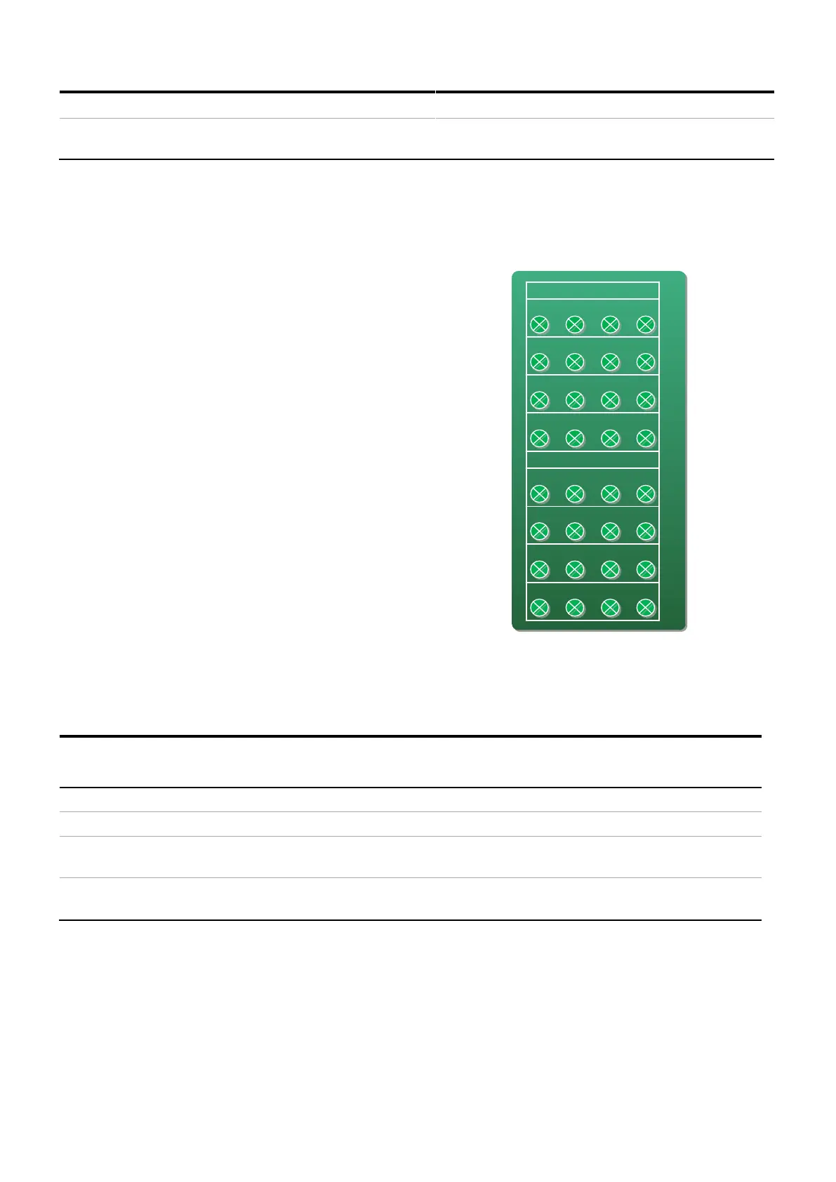
The Mimic Panel represents the status of each
Ultracapacitor module in the enclosure, as they are laid
out in the cabinet. Ultracapacitor Monitor Board logic
is able to distinguish between a disconnected sensor
and a sensible input range. The aim of this
functionality is to prevent any false trips caused by
faulty connections or wiring faults. A warning is given if
these are detected and these inputs are rendered
unprotected i.e. do not have any influence on the
breaker trips. If the LED is solid green then the
capacitor and connection are OK, if not the LED will be
flashing red a number of times, indexing the fault or
warning condition.
The statuses are described in Table 6-3. They are in
order of priority highest to lowest. For example an
overtemperature condition will mask an overvoltage
condition as it is a more severe problem.