Page 104
© Copyright 2021 ABB. All rights reserved.
In addition, the following alarms will be issued for the conditions noted. This assumes the external
disconnect switch is used to open and close the battery charging path to the batteries.
Alarm Inputs: The QS871A is referenced to VBus(-), therefore, all alarm inputs are either alarmed on an
open or a closure to VBus(-) as described below.
• One input closure to VBus(-) for Remote LVD Open (RO) from external source (J3 pins 1 and 2)
• One input to Fuse Input Major alarm upon closure to VBus(-), for distribution protector open alarms (J1 pin 7)
• One input to Open String alarm upon closure to VBus(-) for battery circuit breaker open alarms (J1 pin8)
Reverse Battery Protection: The QS871A will prevent the closure of the battery contactor when it
senses batteries have been connected in reverse polarity. The QS871A will keep the contactor
disconnected and generate an appropriate alarm. When a battery disconnect breaker is used to take
battery strings off-line for servicing, care must be taken to ensure battery connections are correct at
the disconnect switch.
Manual LVD Contactor Connect: This feature allows the Infinity NE or any other power system to
resume powering the load after low voltage disconnect of batteries. Fully depleted battery strings can
be replaced with fully charged strings. Once the strings have been installed, depressing the Manual LVD
Contactor switch on the front of the QS871A module will result in the LVBD contactor closing. Continue
to depress the switch until the Green LED stops flashing and displays a continuous green color. This
indicates acceptance of the command and permanent closure of the contactor. Releasing the switch
prior to the continuous green LED will result in the contactor opening and removing power to the load.
External Shunt Monitoring Input (J1 pins 4 and 5): The shunt must be in the VBus(-) leg to maintain
proper reference with the QS871A module. These inputs are for the system controller to read battery or
load currents. The polarity of the connections must be positive during battery discharge.
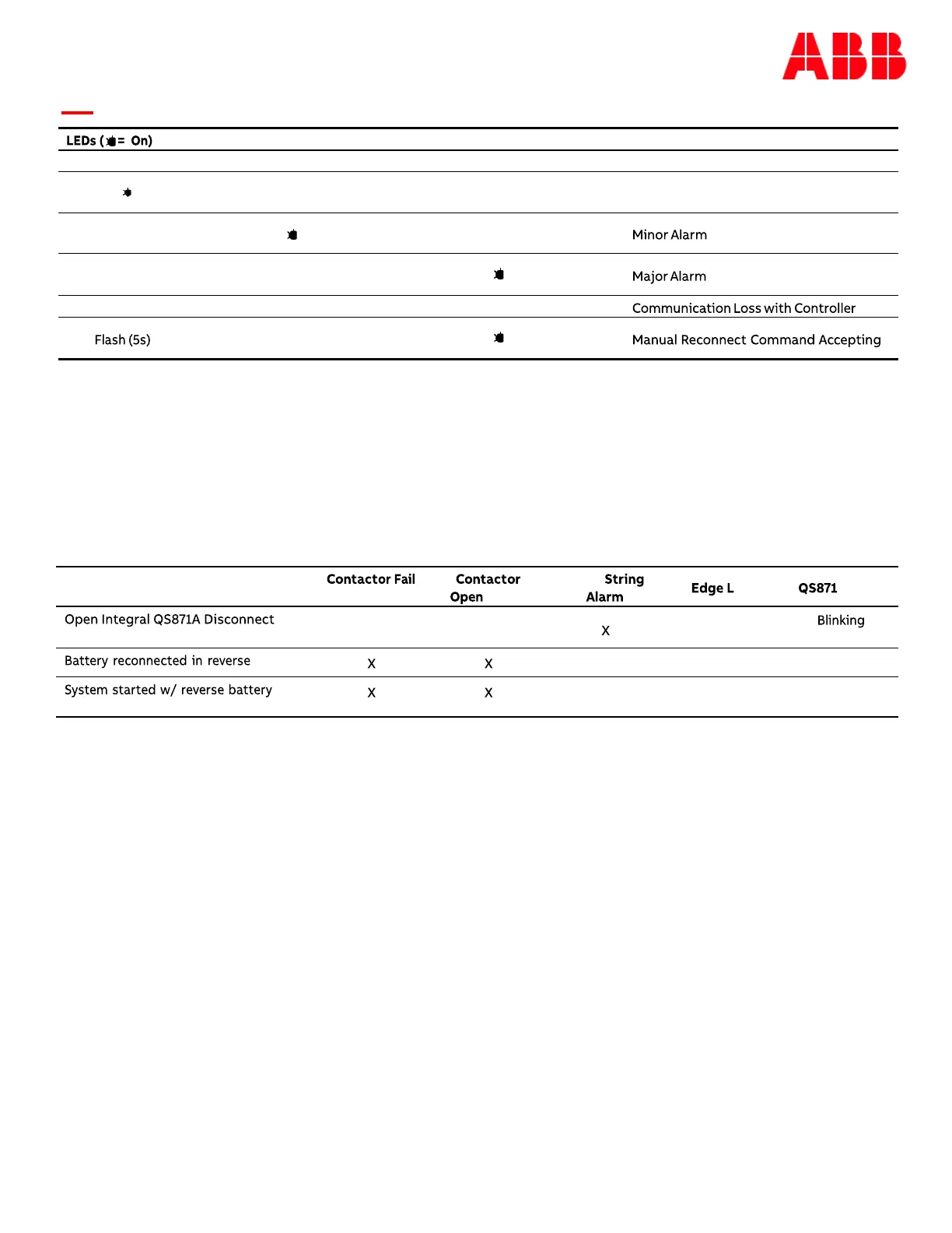
Contactor Management: Controls and monitors one load or battery non-latching contactor.
Green Amber Red Condition
Normal
Flashing
Condition
Alarm Alarm
Open
ED LED
Switch
RED
AMBER
polarity
RED RED
polarity
RED RED