Page 96
© Copyright 2021 ABB. All rights reserved.
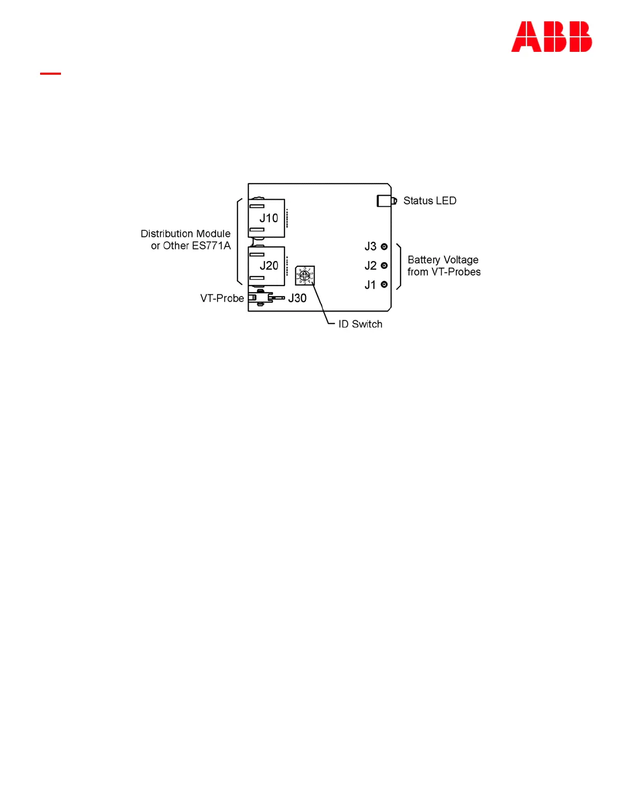
The Pulsar Edge can monitor up to six ES771A modules. Each ES771A module is individually addressed
so that specific mid-string voltages can be displayed and identified. A seven-position rotary ID switch
located on the unit must be set to a unique address number otherwise an ID conflict alarm will be
generated. Units are shipped out of the factory with a default ID setting of “one”. If additional units are
to be in the system the ID must be reconfigured. Note: there are systems that are shipped with ES771A
units installed and with proper configuration.
Following is a brief description of the interfaces on the QS873A VT-Probe depicted above.
J10, J20
RJ-45 receptacles that connect the ES771A to other ES771As or the 1-Wire interface port of the
controller or system provided 1-wire interface. Typical cables utilized are the (CC848791500, 4”) or
(848652947, 10’) cable.
J30
Connects the ES771A to the first QS873A VT-Probes using either the (CC848791517, 2.5’), the
(CC848797290, 6’) or the (848719829’, 10’) cables.
J1, J2, J3
Snap-fit connectors for the mid-string voltage signal wire (Brown) from the VT-Probes.
ID Switch
A seven-position rotary ID switch is used by the Pulsar Edge to uniquely address each ES771A in the
system. A setting of “0” produces and invalid ID alarm. Valid ID settings are from 1 through 6. Units
shipped from the factory have a factory default ID setting of “one”.
Status LED
The module illuminates its green LED when plugged into the 1-wire network and with the VT-probe
attached to negative battery terminal of the mid-string voltage. The LED will illuminate red when the
controller determines that one or more of the strings from the unit has exceeded the Mid-String
Voltage threshold and time considerations.
Figure 19 ES771A Remote Voltage Monitor Module