Page 15
© Copyright 2021 ABB. All rights reserved.
Product Description
Overview
ABB rectifiers accept alternating current (ac) power and rectify it to produce direct current (dc) power
for powering external equipment (loads). Converters accept the dc output from rectifiers or other
sources and convert it to various regulated output dc levels also needed for powering external
equipment (loads). Batteries, generators, and UPS are typically used to provide backup power when ac
is lost. Batteries are connected in parallel for additional capacity with the rectifier outputs through
appropriate breakers and contactor disconnects. DC power is distributed through distribution panels
with various protectors and contactors. These rectifiers, backup systems, and distribution
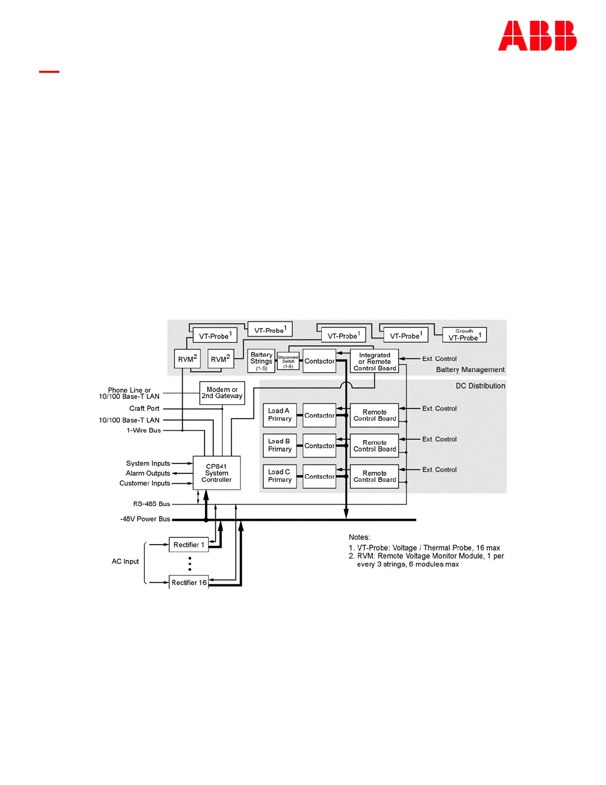
components are all managed by the Pulsar Edge system controller. The following figure depicts a
generic representation of the system controller and its relationship in a power system. The
components depicted and their associated features as they relate to the system controller will be
discussed in this manual.
Configurations
The main “841” microprocessor board comprises the Pulsar Edge family of power system controllers.
This controller is designed to fit a variety of systems and applications. Systems utilizing this controller
are designed to allow the controller be quickly installed or removed from its allocated position through
a simple thumb-screw or insertion fit without having to remove input output cable attachments to the
unit. The input and output cable assemblies are connectorized and can quickly be removed or installed
Figure 6 General Power System Block Diagram