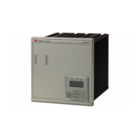
Numerical generator protection
ABB Switzerland Ltd
Utility Automation
REG316*4
1MRK502004-Ben
Page 14
Technical Data
Functions
Table 10: Thermal overload function (49)
· Thermal image for the 1st. order model.
· Single or three-phase measurement with detection of maximum phase value.
Settings:
Base current I
B
0.5 to 2.5 I
N
in steps
of 0.01 I
N
Alarm stage 50 to 200% J
N
in steps
of 1%
J
N
Tripping stage 50 to 200%
J
N
in steps
of 1%
J
N
Thermal time constant 2 to 500 min in steps of 0.1 min
Accuracy of the thermal image ±5%
J
N
(at f
N
) with protection c.t.'s
±2% J
N
(at f
N
) with core-balance c.t.'s
Table 11: Definite time current function (51DT)
· Over and undercurrent detection.
· Single or three-phase measurement with detection of the highest, respectively lowest phase current.
· 2nd. harmonic restraint for high inrush currents.
Settings:
Pick-up current 0.02 to 20 I
N
in steps of 0.01 I
N
Delay 0.02 to 60 s in steps of 0.01 s
Accuracy of the pick-up setting (at f
N
) ±5% or ±0.02 I
N
Reset ratio
overcurrent
undercurrent
>94 % (for max. function)
<106 % (for min. function)
Max. operating time without intentional delay 60 ms
Inrush restraint
pick-up setting
reset ratio
optional
0.1 I
2h
/I
1h
0.8
Table 12: Definite time voltage function (27/59)
· Over and undervoltage detection
· Single or three-phase measurement with detection of the highest, respectively lowest phase voltage
Also applied for detection of:
· stator ground faults (95%)
· rotor ground faults (requires external measuring bridge YWX111 and coupling capacitors)
· inter-turn faults
Settings:
Pick-up voltage 0.01 to 2.0 U
N
in steps
of 0.002 U
N
Delay 0.02 to 60 s in steps of 0.01 s
Accuracy of the pick-up setting (at f
N
) ±2% or ±0.005 U
N
Reset ratio (U ³0.1 U
N
)
overvoltage
undervoltage
>96% (for max. function)
<104% (for min. function)
Max. operating time without intentional delay 60 ms

 Loading...