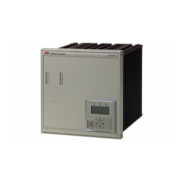
Numerical generator protection REG316*4
1MRK502004-Ben
Page 26
Technical Data Func-
tions (cont’d)
Technical Data Func-
tions (cont’d)
ABB Switzerland Ltd
Utility Automation
Table 37: Rotor earth fault protection (64R)
Table 38: Pole slip protection (78)
Features:
· Continuous supervision of the insulation level and calculation of the earthing (grounding) resistance
· Alarm and tripping values are entered resp. measured and displayed in kW
Settings:
Alarm stage 100 W to 25 kW in steps of 0.1kW
Delay 0.2 s to 60 s in steps of 0.1 s
Tripping stage 100 W to 25 kW in steps of 0.1kW
Delay 0.2 s to 60 s in steps of 0.1 s
R
ER
900 W to 5 kW in steps of 0.01kW
Coupling capacity 2 mF to 10 mF
Reset ratio 110%
Accuracy 0.1 kW to 10 kW <10%
Starting time 1.5 s
Functional requirements:
- total rotor earthing capacity 200 nF to 1mF
- rotor earthing resistance R
PR
100 W to 500 W
- rotor earthing resistance R
ER
900 W to 5 kW
- coupling capacity 4 mF to 10 m F
- time constant T = R
ER
, x C = 3 to 10 ms
The actual earthing resistance R
ER +
R
PR
have to be calculated in accordance with the User’s Guide.
The 100% rotor earth fault protection function always requires an injection unit type REX010 and an injec-
tion transformer block type REX011 which are connected to the plant via coupling capacitors.
Features:
· Recording the pole wheel movements from 0.2 Hz to 8 Hz
· Differentiation of the pendulum center inside or outside of the generator-transformer block zone by two
independent tripping stages
· Adjustable warning angle for pole wheel movements
· Number of slips adjustable before tripping
Fig. 11 Characteristic of the function
Settings:
ZA (system impedance) 0 to 5.0 U
N
/l
N
in steps of 0.001
ZB (generator impedance) -5.0 to 0 U
N
/l
N
in steps of 0.001
ZC (impedance step 1) 0 to 5.0 U
N
/l
N
in steps of 0.001
Phi 60° to 270° in steps of 1°
warning angle 0° to 180° in steps of 1°

 Loading...