11.4.3.1 Phase-to-phase faults
ZAngPP
ZPP
1
23
Ohm/phase
R
X
IEC07000009-4-en.vsd
50%
IEC07000009 V4 EN
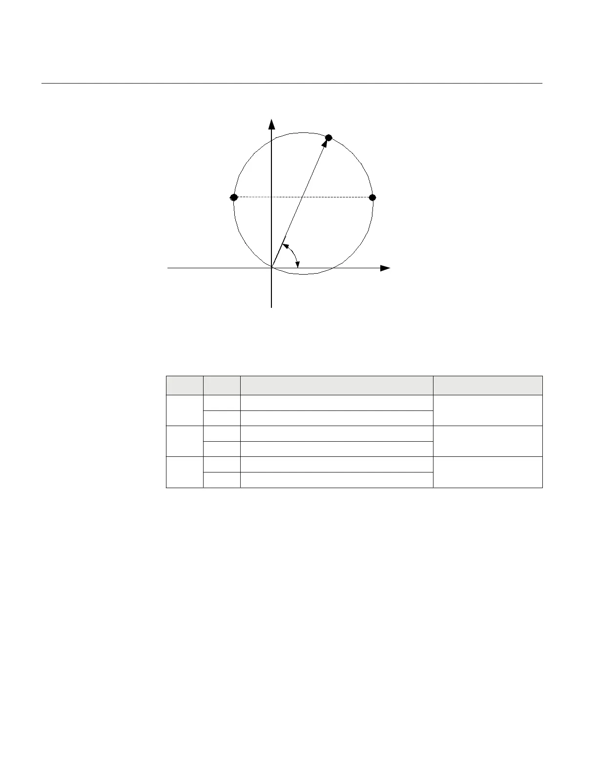
Figure 27: Proposed test points for phase-to-phase fault
Table 22: Test points for phase-to-phase (ohms / phase)
Test
points
reach Value Comments
1 X ZPP · sin(ZAngPP)
R ZPP · sin(ZAngPP)
2 X 0,5· (ZPP· sin(ZAngPP)
R 0,5·ZPP + ΔR = 0,5·ZPP·(1+cos(ZAngPP))
3 X 0,5·ZPP·sin(ZAngPP)
R 0,5·ZPP - ΔR = 0,5·ZPP(1-cos(ZAngPP))
Change the magnitude and angle of phase-to-phase voltage to achieve impedances at test
points 1, 2 and 3. For each test point, observe that the output signals, PICKUP, PU_x and
PHPH_FLT are activated where x refers to the actual phase to be tested. After the timer
tPP for the actual zone has elapsed, also the signals TRIP, TRPP and TR_x shall be
activated.
11.4.3.2 Phase-to-ground faults
For simplicity, the same test points as for phase-to-phase faults are proposed, but
considering new impedance values.
Section 11 1MRK 504 165-UUS -
Testing functionality by secondary injection
122 Transformer protection RET670 2.2 ANSI
Commissioning manual

 Loading...


