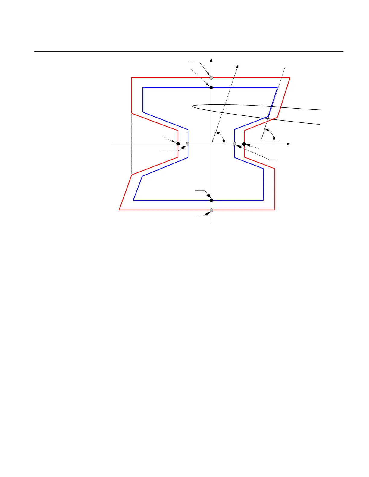
R
X
X1OutFw
X1InFw
1
RLdOutFw
RLdInFw
RLdOutRv
RLdInRv
2
3
4
X1InRv
IEC09000226_1_en.vsd
IEC09000226 V1 EN
Figure 37: Operating principle and characteristic of the power swing detection
function (settings parameters in italic)
Where:
RLdInFw =
RLdOutFw · kLdRFw
RLdInRv =
RLdOutRv · kLdRRv
X1OutFw =
X1InFw + (RLdOutFw -
RLdInFw)
X1OutRv =
X1InRv + (RLdOutFw -
RLdInFw)
11.4.9.1 Verifying the settings
Preconditions
The following output signal shall be configured to binary output available: ZOUT,
measured impedance within outer impedance boundary.
1MRK 504 165-UUS - Section 11
Testing functionality by secondary injection
Transformer protection RET670 2.2 ANSI 143
Commissioning manual

 Loading...


