ZAngPG
50%
Ohm/loop
R
X
ANSI07000010-1-en.vsd
ANSI07000010 V1 EN
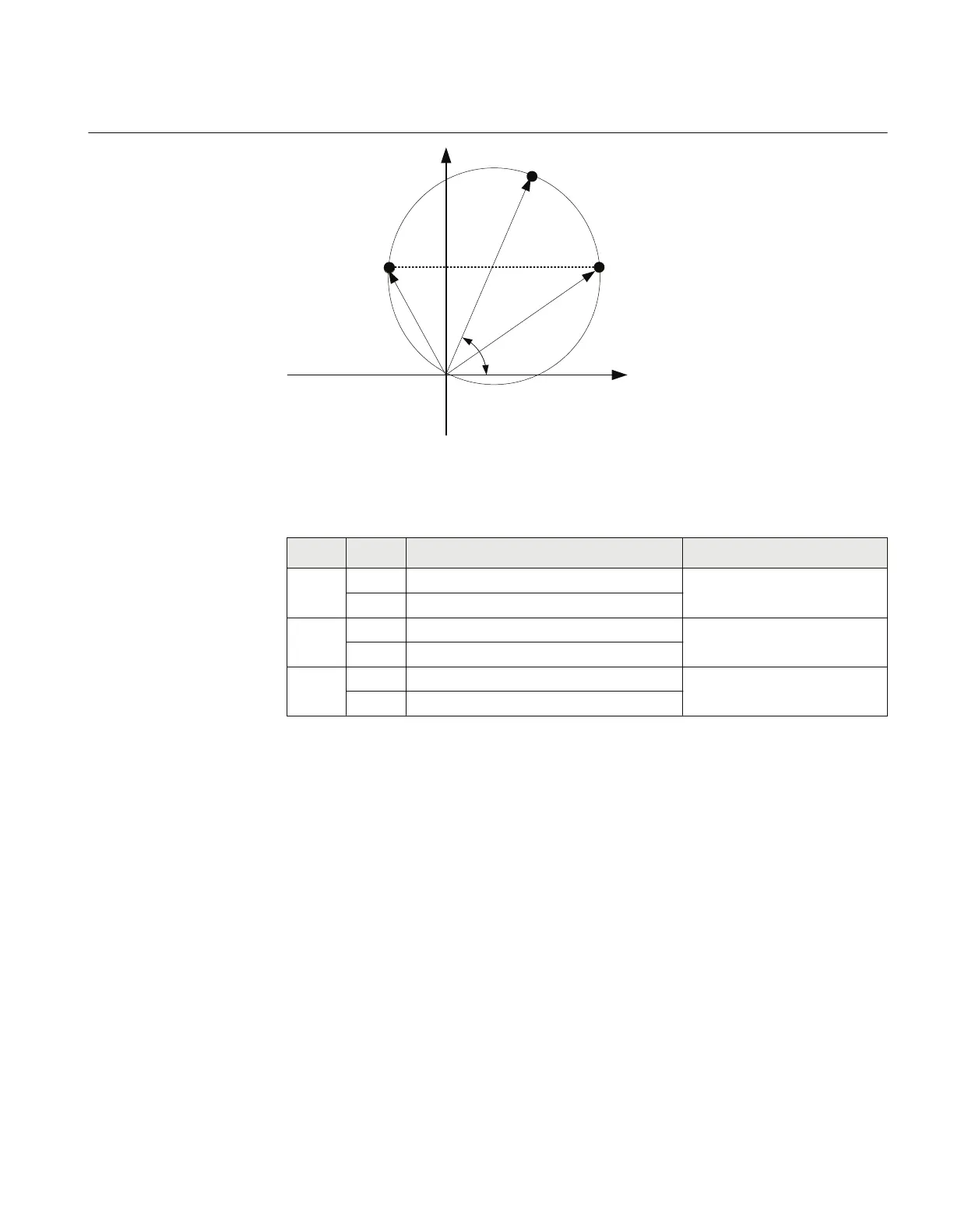
Figure 28: Proposed test points for phase-to-ground faults
Table 23: Test points for phase-to-ground loops A-B (Ohm/Loop)
Test
points
Reach Value Comments
1 X ZPG · sin(ZAngPG)
R ZPG · cos(ZAngPG)
2 X 0,5·ZPG · sin(ZAngPG)
R 0,5·ZPG + ΔR = 0,5·ZPG · (1 - cos(ZAngPG))
3 X 0,5·ZPG·sin(ZangPG)
R 0,5·ZPG - ΔR = 0,5·ZPG · (1 - cos(ZAngPG))
Check also in the same way as for phase-to-ground fault for each test point that the output
signals PHG_FLT, are activated where x refers to the actual phase to be tested. After the
timer tPG for the zone has elapsed, also the signals TRIP, TRPG and TR_x shall be
activated.
11.4.4 Faulty phase identification with load encroachment FMPSPDIS
(21)
There is no specific test routine for this function. The function is tested in conjunction with
other impedance (mho) functions.
1MRK 504 165-UUS - Section 11
Testing functionality by secondary injection
Transformer protection RET670 2.2 ANSI 123
Commissioning manual

 Loading...


