EasyManuals Logo

ABB RET670 Commissioning Manual

ABB RET670
328 pages
To Next Page IconTo Next Page
To Previous Page IconTo Previous Page
Page #92 background imageLoading...
Page #92 background image
IEC140000145-1-en.vsd
IEC140000145 V1 EN
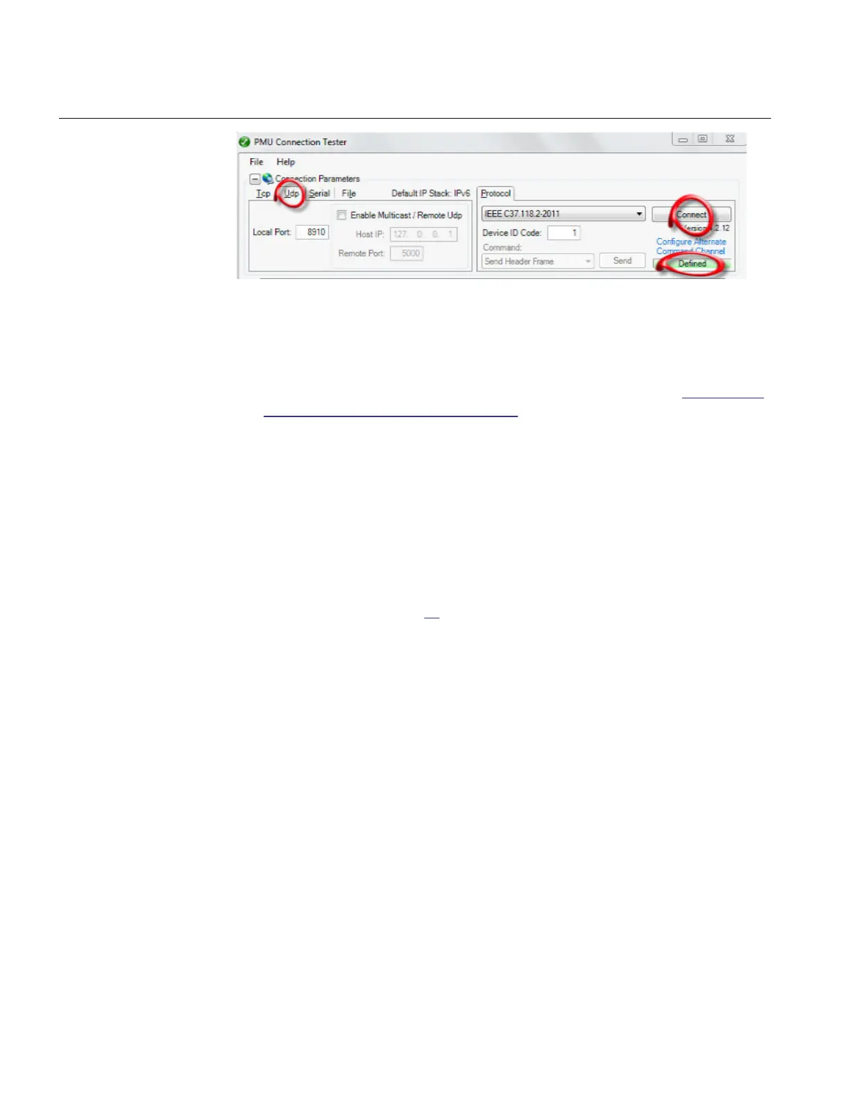
Figure 17: Verifying the UDP communication using PMU Connection Tester
Now it should be possible to see the streaming synchrophasor data.
Verify the communication by following the same steps as in section Verifying the
IEEE C37.118/1344 TCP communication.
9.6 Optical budget calculation for PMU - PDC
communication
Most of the times, the PMU IEDs are located in the substations. A local PDC might be
located in the substation. For communications within the substation or between the IED
and the WAN/LAN access point, it is important to know what is the optical budget
available. The graph in Figure
18 shows the dynamic range available for a PMU – PDC
configuration using typical OEMs.
Section 9 1MRK 504 165-UUS -
Establishing connection and verifying the IEEE C37.118/1344 communication
86 Transformer protection RET670 2.2 ANSI
Commissioning manual

Table of Contents

Other manuals for ABB RET670

Questions and Answers:

Question and Answer IconNeed help?

Do you have a question about the ABB RET670 and is the answer not in the manual?

ABB RET670 Specifications

General IconGeneral
Rated Frequency50/60 Hz
InputsAnalog and binary inputs
ApplicationProtection of power systems
Communication ProtocolsIEC 61850, DNP3, Modbus
Operating Temperature Range-25°C to +55°C
MountingRack mounted
Number of Binary InputsUp to 48
Number of Binary Outputs32
Protection FunctionsOvercurrent Protection
OutputsBinary outputs
EnclosureIP 54
TypeLine Differential Protection
Number of Analog Inputs24

Related product manuals