Test the correct functionality by simulating different kind of faults. Also check that sent
and received data is correctly transmitted and read.
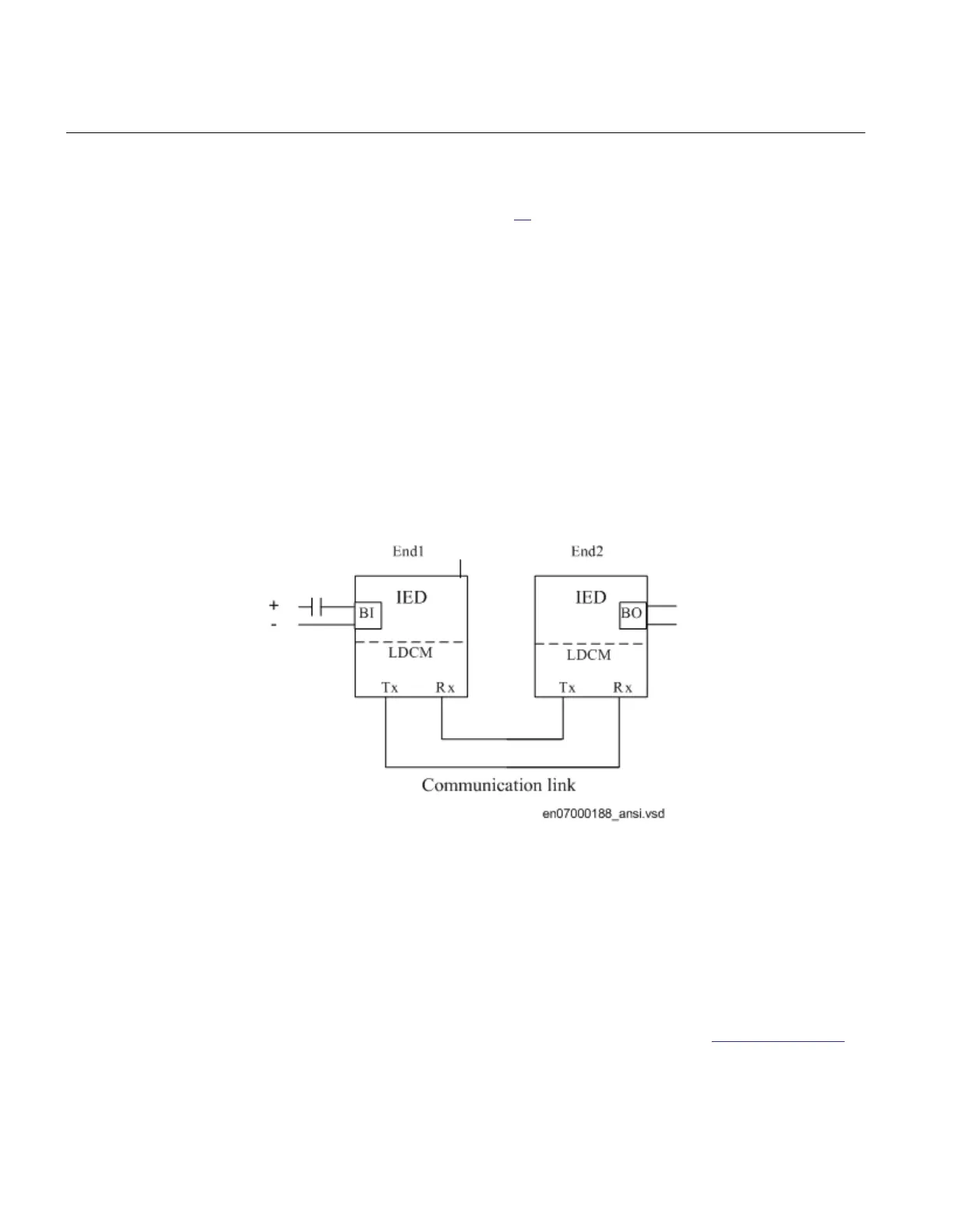
A test connection is shown in figure 55. A binary input signal (BI) at End1 is configured
to be transferred through the communication link to End2. At End2 the received signal is
configured to control a binary output (BO). Check at End2 that the BI signal is received
and the BO operates.
Repeat the test for all the signals configured to be transmitted over the communication
link.
ANSI07000188 V1 EN
Figure 55: Test of RTC with I/O
11.17 Basic IED functions
11.17.1 Parameter setting group handling SETGRPS
Prepare the IED for verification of settings as outlined in section "Preparing for test" in
this chapter.
Section 11 1MRK 504 165-UUS -
Testing functionality by secondary injection
284 Transformer protection RET670 2.2 ANSI
Commissioning manual

 Loading...


