X1
R
X
85%
1
3
5
2
6
4
50% RLdFwd
ArgNegRes
0.5·RFltFwdPP
LdAngle
ANSI09000735-1-en.vsd
ArgDir
60°
)/( phaseW
)/( phaseW
7
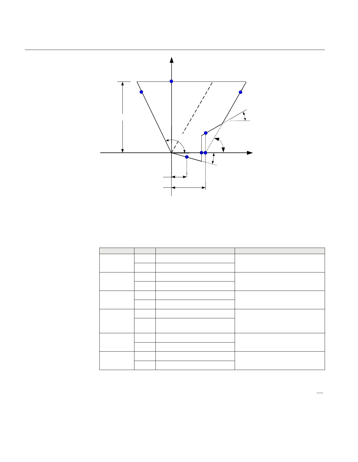
ANSI09000735 V1 EN
Figure 32: Operating characteristic for phase selection function, forward direction
phase-to-phase faults
Table 26: Test points for phase-to-ground loop CG (Ohm/loop)
Test point
Value Comments
1 X [X1+XN] XN=(X
0
-X
1
)/3
R 0
2 X 0
R RLdFwd
3 X 0.85·[X1+XN] R≈0.491·(X1+XN)+RFFwPE
R 0.85·[X1+XN]·1/tan(60°)+RFFwPE
4 X 0.85·[X1+XN]
R -0.85·[X1+XN]·
tan (AngNegRes-90°)
5 X RFltFwdPG·tan (LdAngle)
R RFltFwdPG
6 X -0,5·RLdFwd·tan (ArgDir)
R 0,5·RLdFwd
The table showing test points for phase-to-ground loops is used together with figure 31.
Section 11 1MRK 504 165-UUS -
Testing functionality by secondary injection
130 Transformer protection RET670 2.2 ANSI
Commissioning manual

 Loading...


