V
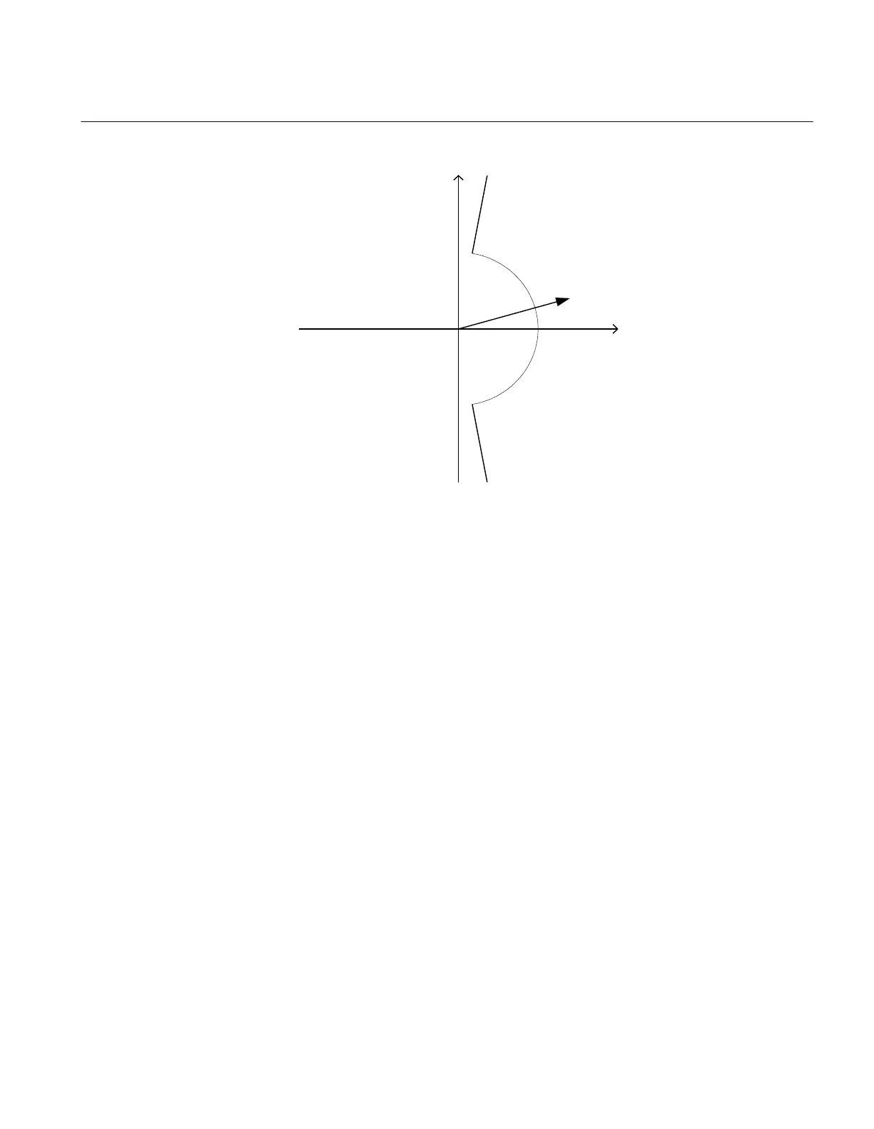
ref
=-3V
0
Operate area
3I
0
RCA = 0º
ROA = 80º
ANSI06000652-2-en.vsd
ANSI06000652 V2 EN
Figure 47: Example characteristic
Non-directional ground fault current protection
Procedure
1. Measure that the trip current is equal to the INNonDirPU setting.
The function activates the PICKUP and PUDIRIN output.
2. Measure the trip time of the timer by injecting a current of 200% of the trip value.
3. Compare the result with the expected value.
The expected value depends on whether definite time tINNonDir or inverse time was
selected.
4. Continue to test another function or complete the test by setting the test mode to
Disabled.
Residual overvoltage release and protection
Procedure
1. Measure that the trip voltage is equal to the VN_PU setting.
The function activates the PICKUP and PUVN signals.
2. Measure the trip time by injecting a voltage 1.2 times set VN_PU trip value.
3. Compare the result with the set tVN trip value.
1MRK 504 165-UUS - Section 11
Testing functionality by secondary injection
Transformer protection RET670 2.2 ANSI 189
Commissioning manual

 Loading...


